7
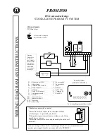
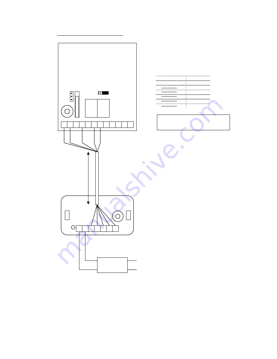
Wiring diagram auxiliary reader
3
2
V
1
E
M B
O
C
T
5
12
RL1
RL2
3
2
1
ST1
ST2
1
3
I1
3
2
V
1
4
5
12
Distance :
minimum 60cm
maximum 50 m
Auxiliary reader
(terminal connections)
Input voltage
12V ~ or =
230V~
12
Power supply
V
Power supply
1 1
Data
2 2
Buzzer
3 3
Green LED
M 4
Common
5
5
Red LED
PROMI500
Aux.
Reader
It is recommended to use a separate
power supply for the auxiliary reader

