cdvigroup.com
12
INSTALLATION MANUAL
EN
STAR1M - Mullion Mifare
®
card reader
4] OPERATION MODES
Dipswitch
Standalone mode
(page 13)
Wiegand mode
(
page 18)
1
OFF
ON
2
OFF
ON
OFF
ON
Change the
Master card
NORMAL
operation
Dipswitch 3
option
44 bits
3
OFF
ON
OFF
ON
Shadow mode
(page 15)
Standard mode
(page 16)
26 bits
30 bits
4
Not assigned
The different dipswitch positions are used to switch the STAR1M to a
standalone system or to a Mifare
®
reader.
5] WIRING DIAGRAM
C56
C58
C61
1
MM10
4
3
2
1
ON
ON
ON
ON
L7
Q6
Q7
Q8
R77
R78
R79
P1
1
P3
BZ3
C6
C24
C59
-
+
MM1
MM14
CR3
+
-
CR10
CR25
CR26
CR24
MM3
MM15
CR12
CR13
CR15
I1
+
-
+
-
MM16
CR22
P2
-
+
CR19 CR21 CR20
CR28
CR27
CR29
CR11
R70
R67
R68
R64
R69
R65
C68
CR30
Wire
colors
Wiring table
Standalone mode
Wiegand mode
Red
12Vdc
12Vdc
Black
0 V
0 V
Green
/
Data 0
White
/
Data 1
Blue
Normally open
/
Grey
Common
/
Purple
Normally closed
/
Brown
Request-to-exit input
Buzzer input
Yellow
/
Green LED input
Orange
/
Red LED input
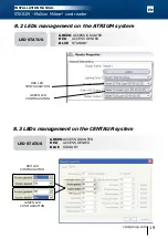
LEDs on start-up:
- Green (1s)
- Red (1s)
- Blue + BEEP (1s)
LEDs during routine operation:
- Standby: Blue
- When a tag is read: Green or red
To switch operation mode, please reboot the STAR1M.


