background image

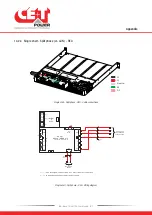
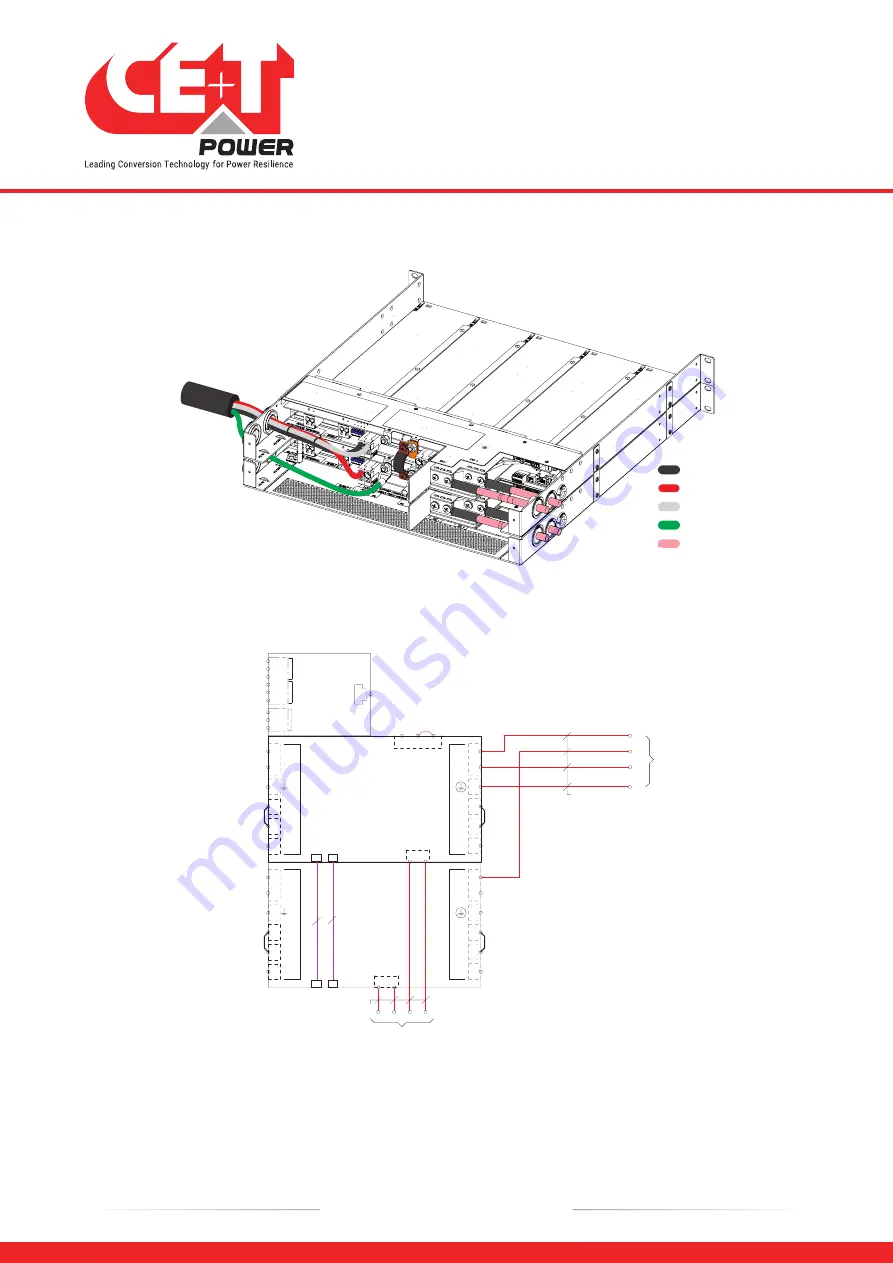
14.2.6  Two shelves - Split phase (L1-L2-N) - REG

L1
L2
Neutral
PE
DC

Split phase - REG - Cable connections

*

2

*

3

*

2

NO
NC
C
NO
NC
C

DIG IN

RELAY

2

RELAY

1

INVIEW

S

SLOT

(-) D2

(-) C

(+) D1

8

6

L1

L1

X1

X6

X96

L1

L1

X91

X94

X4

X8

X95

D C

+

-

AC

OU

T

AC

IN

(4 MODULES INSTALLABLE)

RACK-1

BRAVO / SIERRA 10

L2

L2

L2

L2

N

N

1

2

3

X5

RI/O

*

2

*

2

N

PE

L1

L2

AC OUTPUT

2x120/208VAC /

2x120/240VAC

DC+ DC- DC+ DC-

DC INPUT-1-2 48VDC

2AWG

35MM2

8

6

L1

L1

X1

X6

X96

L1

L1

X91

X94

X4

X8

X95

AC

OU

T

AC

IN

(4 MODULES INSTALLABLE)

RACK-2

BRAVO / SIERRA 10

L2

L2

L2

L2

N

N

D C

+

-

4AWG

25MM2

COM BUS

2* ------> AC OUTPUT L1 & L2 INTERLINK CONNECTION

3* ------> TO BE REMOVED WHEN EXTERNAL REMOTE USED

Split phase - REG - Wiring diagram

Appendix

56 

- Bravo 10 - 48/120 - User manual - v1.1

Summary of Contents for BRAVO 10 - 48/120

Page 1: ...gium www cet power com info cet power com DUAL INPUT INVERTER Commercial Power as default source AC BACKUP IN A DC ENVIRONMENT Leverage your existing DC infrastructure ONE STOP SHOP Wide output power...

Page 2: ...Inverter 13 5 1 2 Specifications 13 5 1 3 Sub rack 15 5 2 Controller Unit 15 5 2 1 Inview Slot 15 5 2 2 Inview S 17 5 2 3 Inview S Connections 17 6 System Installation 18 6 1 Transformer and Generator...

Page 3: ...ing 40 8 2 Controller Inview Slot 41 8 2 1 Removal 41 8 2 2 Inserting 41 8 3 Controller Inview S 42 8 3 1 Panel Mounting 42 9 Finishing 43 10 Commissioning 44 10 1 Check list 45 11 Trouble Shooting an...

Page 4: ...4 Bravo 10 48 120 User manual v1 1 14 2 5 Two shelves Split phase L1 L2 N 55 14 2 6 Two shelves Split phase L1 L2 N REG 56 14 2 7 Three phase L1 L2 L3 N 57 14 2 8 Three phase L1 L2 L3 N REG 58...

Page 5: ...elease Note Version Release date DD MM YYYY Modified page number Modifications 1 0 07 02 2022 First release of the manual 1 1 09 09 2022 Updated the shelf connections 5 Bravo 10 48 120 User manual v1...

Page 6: ...p solution that unlike most used UPS s Maximizes the operator s applications uptime Operates with lowest OPEX Provides best protection to disturbances Optimizes footprint Our systems are Modular Truly...

Page 7: ...col LAN Local Access Network MBB Measure Box Battery MBP Manual By pass MET Main Earth Terminal MIB Management Information Base N Neutral NTP Network Time Protocol NUA Non Urgent Alarm PCB Printed Cir...

Page 8: ...ance are required to have knowledge or experience related to electrical maintenance Please follow the procedures contained in this Manual and note all the DANGER WARNING AND NOTICE marks contained in...

Page 9: ...e terminated with no voltage power applied de energized The safety standard IEC EN62040 1 1 requires that in the event of an output short circuit the inverter must disconnect in 5 seconds maximum The...

Page 10: ...ucted on a system unit make sure that AC input voltage and DC input voltage are disconnected CAUTION Risk of electric shock Inverter modules and shelves contain capacitors for filtering and energy sto...

Page 11: ...output sine wave is constant and disturbance free regardless of the active source The ECI works according to True Redundant Structure TRS that features decentralized and independent logic redundant c...

Page 12: ...he safe mode is used in extremely harsh environments such as railways Under such conditions it provides extra isolation against mains borne disturbances 4 3 EPC Mode Mains input AC is the primary sour...

Page 13: ...Shelf T611330201 T614330000 Cooling Audible noise Fan forced cooling 65db 1meter MTBF 200 000 hrs at 30 C 80 load MIL 217 F Dielectric strength DC AC 4300 Vdc RoHS Compliant Operating T Relative Humi...

Page 14: ...Load impact recovery time 10 90 0 4 ms Nominal current 8 3 A 120 Vac Crest factor at nominal power 3 1 for load P F 0 7 Short circuit clear up capacity 0 20 ms 34 A Short circuit current after 20 ms 1...

Page 15: ...te in the module shelf and reduces the additional space in the cabinet It allows the user to easily access the system information through inbuilt powerful LCD touch screen graphic display In addition...

Page 16: ...is assigned for MBP operation if used Digital Input 2 is assigned for Surge Arrester if used Output Relays K1 and K2 Two output relays are available and can be used for Major and Minor Alarms CAN Mod...

Page 17: ...2 Digital Input 1 Output Relay 2 Output Relay 1 Power 12 Vdc NC PE NO NO CAN iso RS485 ETH USB CE T COM CE T COM port is dedicated to establish connection between Inview S and Bravo 10 shelf ETH port...

Page 18: ...st be C UL US or CSA listed They must be sized according to the rated current of the converter system and to the customer terminal connection Wire all positions for future expansion Input AC Output AC...

Page 19: ...e Hex socket screw with Allen key till it touches behind the metal part 3 Fix the other end of the mounting kit at cabinet rear using the M6 Philips head screw and cage nut 4 Similarly assemble anothe...

Page 20: ...top and bottom of the protection cover Note Refer to section 14 1 page 50 to know more about knockout dimensions 3 Connect the power and signal cables with supplied screws refer section 6 4 2 page 21...

Page 21: ...ions 6 4 2 1 EPC Version Inview Slot Terminals Refer to section 6 4 9 page 27 DC DC AC OUT AC IN L1 PE L2 AC IN AC OUT L2 N N PE L1 Bravo 10 48 120 Shelf Rear Details 6 4 2 2 REG Version No AC In Invi...

Page 22: ...T 1 terminals A single phase system is 120 Vac from L to N Input and output are the same consisting of 2 wires PE Ground Note The jumper cable should be a minimum of 12 AWG DC DC AC OUT AC IN L1 J1 J2...

Page 23: ...th two shelves the Jumpers J1 and J2 should be present on both shelves For connection details refer to sections 14 2 5 page 55 and 14 2 6 page 56 In each phase the number of modules should be equal DC...

Page 24: ...below image CET Bus and Neutral cables must be paralleled if it is multiple shelves Note In each phase the number of modules should be equal DC CET Bus cable 6 8 Pin DC Shelf 1 Shelf 2 Shelf 3 Neutra...

Page 25: ...e ground is floating The inverter UPS will operate without problem but you may infringe the local regulation L1 L2 L3 N PE Local TFO Circuit Breaker Inverter UPS Model Configuration Maximum Capacity C...

Page 26: ...kW 74 A 100 A 3 AWG S61A33CDD05SNF00G00H 5 kVA 4 kW 93 A 125 A 2 AWG S61A63CDD04SNF00G00H Split Phase 3 Wires L1 L2 N 4 kVA 3 2 kW 74 A 100 A 3 AWG S61A63CDD08SNF00G00H 8 kVA 6 4 kW 2 x 74 A 2 x 100 A...

Page 27: ...ear shelf is for Inview Slot It can only be accessed if Inview Slot connected to that shelf 6 Pin BUS B 8 Pin BUS A ON OFF CE T COM port Remote To Inview S K1 K2 NO NO NC NC C C Power PE D1 D2 CAN Mod...

Page 28: ...Closed Closed Normal operation All Green Warning If remote ON OFF is not used pin 2 and 3 MUST be bridged together 6 4 9 2 Internal bus BUS A BUS B In a la carte system Internal bus is pre installed a...

Page 29: ...e properly Blinking green orange alternatively Recovery mode Permanent orange Starting mode Blinking orange Modules cannot start Check Inview Blinking red Recoverable fault Permanent red Non recoverab...

Page 30: ...ext and the previous screen In some screens up and down arrows appear at the top of the page indicating more contents are present 2 Status bar The status bar appears throughout the interface and illum...

Page 31: ...Battery DC Wi Fi Refresh module list Cut off alarms AC In details Current Voltage Hertz Active power kW Apparent Power kVA DC details Current Voltage Power AC In details Current Voltage Active power...

Page 32: ...ttons for next and previous page In some pages Up and Down navigation buttons appear at the right side indicating more contents are present 2 Information Area Provides information about the correspond...

Page 33: ...power AC Out details Voltage Current Active power Apparent power Power factor DC details Voltage Battery current Battery power Load current Load power Battery temperature AC In details Voltage Curren...

Page 34: ...igured converters 9 Installed power It is the total power of the configured converters including redundancy Moreover it is a user configuration based upon the system capacity 10 Available power It is...

Page 35: ...ology selection Administration Home Dashboard Monitoring Energy System Converter System Converter Systems DC Systems Sensors Actuators DC System Reporting Users Files Explorer CANbus Devices Dashboard...

Page 36: ...ome Mozilla Firefox Safari or Microsoft Edge Inview Slot S and X have three login Basic Expert and Admin All three login is password protected The default password for all three logins is 1234 Basic l...

Page 37: ...ts regarding AC Input 2 DC Clicking on the DC region displays the page contains all measurements regarding DC input and output 3 Power System Clicking on the Power System region display the page conta...

Page 38: ...Help and Rename icons are present at right side of the web page Filters Page displays depending upon the filter selection On Board help Provide a short description to help to know about the correspond...

Page 39: ...ts all the parameter changes in the modifications list and saves them in the configuration file Dismiss All Clicking on DISMISS ALL button the controller rejects all the parameter changes in the modif...

Page 40: ...multaneously pull the module using front handle 3 Remove the module from shelf and replace with a new module or dummy cover Push the pin and pull the module Remove the module from shelf Insert the pin...

Page 41: ...ove the module from shelf Insert the pin into the hole Pin Hole 8 2 2 Inserting 1 Place the Inview Slot and slide into the shelf 2 Push the unit firmly until the controller rear part is engaged correc...

Page 42: ...he four latches at the rear side of the Inview S in the panel sheet 3 Connect required connection cables to the Inview S 4 Place the panel sheet in the system and fix it with screws Place the Inview S...

Page 43: ...cables are strained relived Make sure that all breakers are according to recommendation and local regulations Make sure that DC polarity is according to marking Re tighten all electrical terminations...

Page 44: ...t to have all module operating when running on DC and have module failure when AC input recover from fault condition Installation and commissioning must be done and conducted by trained people fully a...

Page 45: ...me parameters should be adapted according to the site condition Switch OFF AC IN and check if system is working on DC Switch ON AC IN and check if system correctly transferred load on AC Switch OFF sy...

Page 46: ...that Inview is present and properly inserted Check remote ON OFF terminal Check the configuration and setting Check threshold level Inverter only run on AC or DC Check AC input present and in range AC...

Page 47: ...guidelines may be requested by email at tech support cetamerica com The RMA number should be mentioned on all shipping documents related to the repair Be aware that products shipped back to CE T Power...

Page 48: ...perature deviation may indicate build up of dust Clean the module by air suction blower or vacuum cleaner Check module system load Check Correct inverter mapping DC group AC group Address Change confi...

Page 49: ...4627 or tech support cetamerica com Normal service hours are 8 00 AM to 5 00 PM Eastern Time Monday through Friday except closing periods for holidays or inclement weather Critical emergency condition...

Page 50: ...1 50 Le Side View 14 1 2 Shelf 484 44 30 C FRONT VIEW 496 45 501 52 522 75 442 85 35 26 50 75 TOP VIEW 43 50 496 45 LEFT VIEW RIGHT VIEW 27 86 15 90 DETAIL A SCALE 1 2 34 90 22 20 DETAIL B SCALE 1 2 1...

Page 51: ...USED 2 DC DC DC INPUT 1 48VDC 4AWG 25MM2 2AWG 35MM2 3 L N PE L N PE AC OUTPUT 120VAC AC INPUT 120VAC 4AWG 25MM2 2 NO NC C NO NC C DIG IN RELAY 2 RELAY 1 INVIEW S SLOT D2 C D1 8 6 L1 L1 X1 X6 X96 L1 L...

Page 52: ...OUTPUT 120VAC 4AWG 25MM2 2AWG 35MM2 3 8 6 L1 L1 X1 X6 X96 L1 L1 X91 X94 X4 X8 X95 DC AC OUT AC IN RACK 1 BRAVO SIERRA 10 L2 L2 L2 L2 N N 1 2 3 X5 RI O 2 AC OUTPUT L1 L2 INTERLINK CONNECTION 1 REG MODE...

Page 53: ...NC C NO NC C DIG IN RELAY 2 RELAY 1 INVIEW S SLOT D2 C D1 8 6 L1 L1 X1 X6 X96 L1 L1 X91 X94 X4 X8 X95 DC AC OUT AC IN 4 MODULES INSTALLABLE RACK 1 BRAVO SIERRA 10 L2 L2 L2 L2 N N 1 2 3 X5 RI O N PE L...

Page 54: ...48VDC 2AWG 35MM2 3 8 6 L1 L1 X1 X6 X96 L1 L1 X91 X94 X4 X8 X95 DC AC OUT AC IN 4 MODULES INSTALLABLE RACK 1 BRAVO SIERRA 10 L2 L2 L2 L2 N N 1 2 3 X5 RI O L1 L2 AC OUTPUT 2x120 208VAC 2x120 240VAC 10AW...

Page 55: ...L2 N N 1 2 3 X5 RI O 2 2 N PE L1 L2 AC OUTPUT 2x120 208VAC 2x120 240VAC N PE L1 L2 AC INPUT 2x120 208VAC 2x120 240VAC DC DC DC DC DC INPUT 1 2 48VDC 2AWG 35MM2 8 6 L1 L1 X1 X6 X96 L1 L1 X91 X94 X4 X8...

Page 56: ...E RACK 1 BRAVO SIERRA 10 L2 L2 L2 L2 N N 1 2 3 X5 RI O 2 2 N PE L1 L2 AC OUTPUT 2x120 208VAC 2x120 240VAC DC DC DC DC DC INPUT 1 2 48VDC 2AWG 35MM2 8 6 L1 L1 X1 X6 X96 L1 L1 X91 X94 X4 X8 X95 AC OUT A...

Page 57: ...1 BRAVO SIERRA 10 L2 L2 L2 L2 N N 1 2 3 X5 RI O 2 2 N PE N PE 8 6 L1 L1 X1 X6 X96 L1 L1 X91 X94 X4 X8 X95 AC OUT AC IN 4 MODULES INSTALLABLE RACK 2 BRAVO SIERRA 10 L2 L2 L2 L2 N N DC 4AWG 25MM2 DC DC...

Page 58: ...DULES INSTALLABLE RACK 1 BRAVO SIERRA 10 L2 L2 L2 L2 N N 1 2 3 X5 RI O 2 2 N PE 8 6 L1 L1 X1 X6 X96 L1 L1 X91 X94 X4 X8 X95 AC OUT AC IN 4 MODULES INSTALLABLE RACK 2 BRAVO SIERRA 10 L2 L2 L2 L2 N N DC...

Page 59: ......

Reviews: