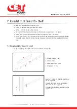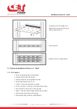
Fix cage nuts (
4
) in the mounting frame.
Slide the shelf in position and fix the shelf
with the supplied screws (
3
).
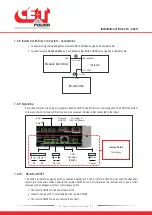
Insert the modules.
Repeat the steps for remaining shelves.
7.2 Electrical installation for Bravo 10 - Shelf
7.2.1 Pre requisites
•
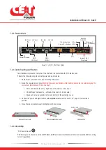
The sub-rack have markings for all terminations.
•
All cables shall be rated at Min 90 deg C.
•
Electrical terminations shall be tightened with 5 Nm.
•
All connection screws are M5 x 12 mm.
•
DC Input - Common (per shelf), check DC polarity.
•
AC Input / AC output - Common (per shelf), check AC phase angle.
•
Wire all positions in the sub-rack for future expansion.
•
Input AC / Output AC / Input DC / Signal cables shall be separated.
•
Cable crossings shall be done in 90 deg angles.
•
Empty inverter positions shall be covered with dummy.
Installation of Bravo 10 - Shelf
19
- Bravo 10 - 48/230 - User manual - v1.2
Summary of Contents for Bravo 10 - 48/230
Page 43: ......

