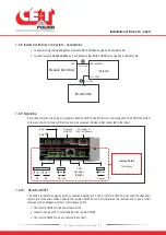
7.2.8 Inview S with Bravo 10 System - Connections
1. Connect module shelf
RJ45 port
and Inview S
CE+T COM
port using RJ45 straight cable.
2. Connect Inview S
CAN/iso RS485
port and Measure Box Battery
CAN1
port using RJ45 straight cable.
Measure Box Battery
Module Shelf
Inview S
CAN 1
RJ45
CAN / iso RS485
CE+T COM
RJ45 Cable
RJ45 Cable
1
2
7.2.9 Signalling
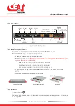
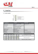
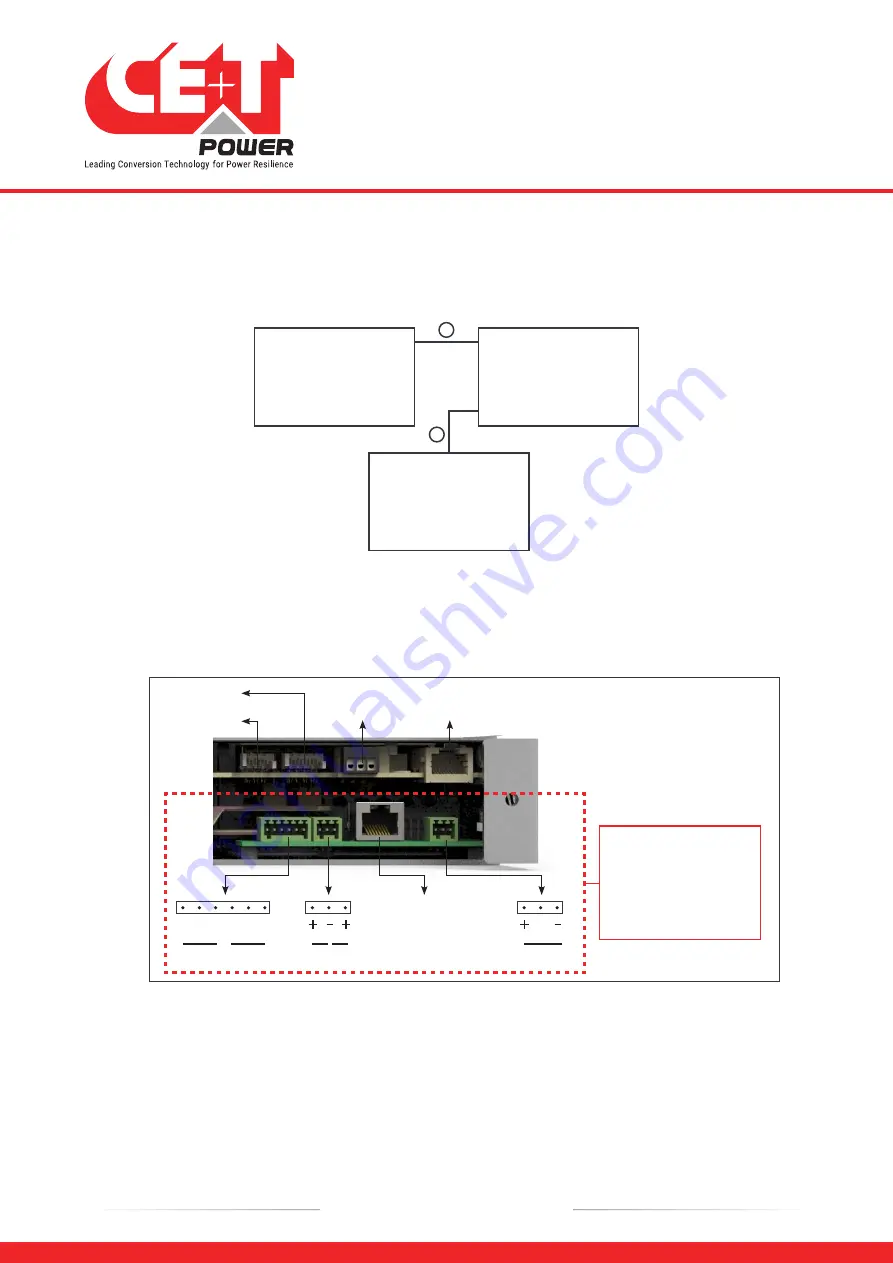
Each shelf comprise of 8 and 6 pin connector, Remote ON/OFF and ETH port for communication. The PCB at the bottom
of the rear shelf is for Inview S Slot. It can only be accessed if Inview S Slot connected to that shelf.
6 Pin
8 Pin
ON/OFF
(CE+T COM port)
Remote
To Inview S
K1
K2
NO
NO
NC
NC
C
C
Power
PE
D1 D2
CAN
Modbus
(RS485)
Inview S Slot
Terminals
7.2.9.1 Remote ON/OFF
The shelf is by default equipped with a connection between pin 3 and 2. If remote ON/OFF is not used the strap shall
remain in all connected shelves. Should the remote ON/OFF be used, all straps must be removed and in one (1) shelf
replaced with a changeover contact or emergency button.
•
The remote ON/OFF switch the output AC OFF.
•
Input AC and input DC is not affected by the remote ON/OFF.
•
The remote ON/OFF can be connected to any shelf.
Installation of Bravo 10 - Shelf
22
- Bravo 10 - 48/230 - User manual - v1.2
Summary of Contents for Bravo 10 - 48/230
Page 43: ......

