10.2.2 By-pass to Normal (Disengage MBP)
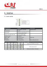
1. Switch ON the DC power and/or connect batteries, and wait for module DC IN LED to turn green.
2. Rotate the MBP Switch (S1) from
BYPASS
to
INTERIM
.
(Wait until the modules turn on and synchronized, approximately 30-60 seconds).
3. Rotate the MBP Switch (S1) from
INTERIM
to
NORMAL
.
WARNING
IF ATS (automatic transfer switch) IS INSTALLED UPSTREAM TO SELECT AC SOURCE. MAKE SURE THAT THE ATS
SWITCH DOES NOT ALLOW TRANSFER BETWEEN AC SOURCE OUT OF SYNC. THE MAXIMUM ALLOWED PHASE SHIFT IS
10°.
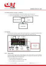
10.3 MBP Auxiliary connection
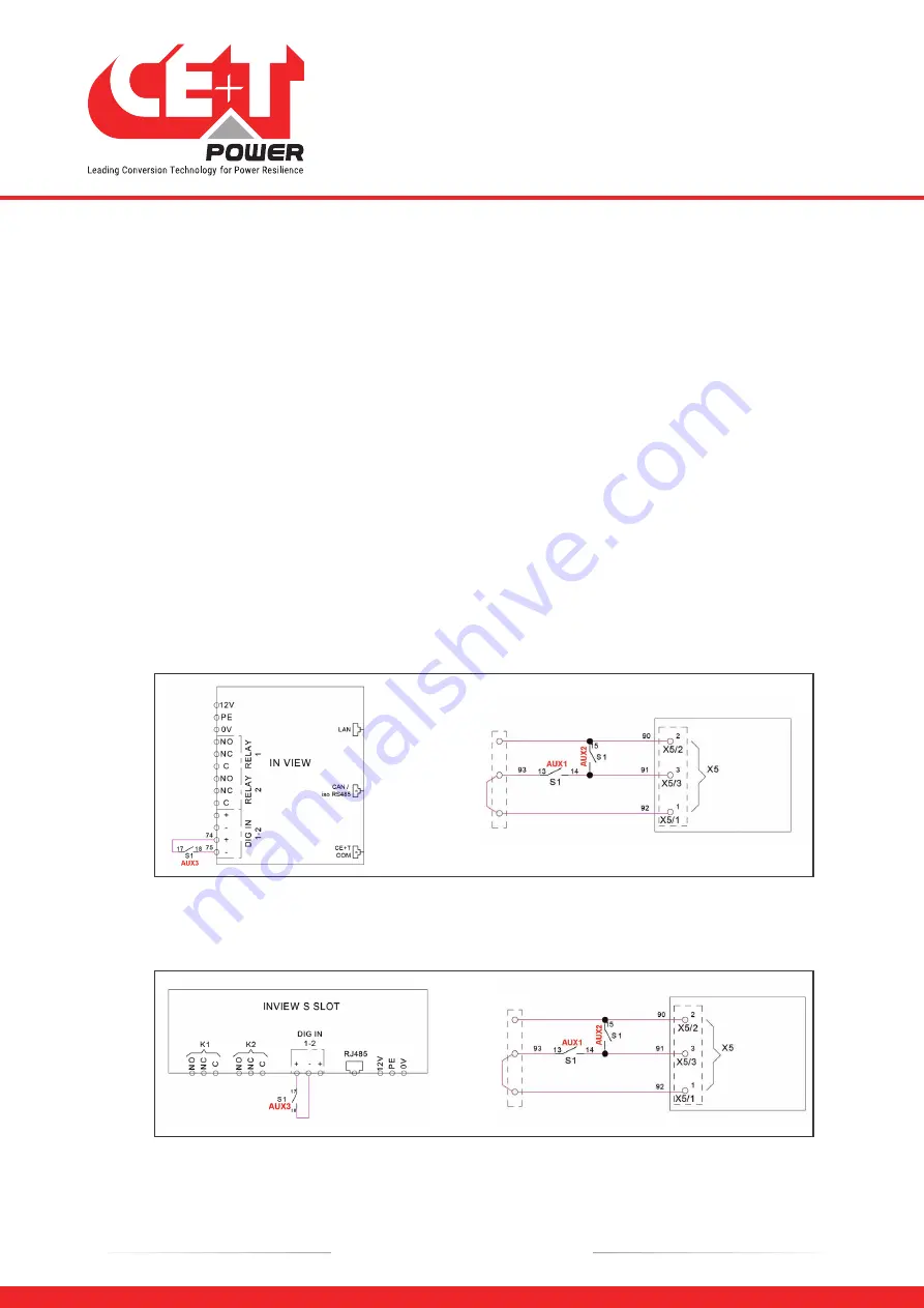
If manual by pass (Single rotary switch) is installed in the system and its auxiliary should be wired as per the following:
Note: The below connection is for a sub-rack system, and auxiliary (Aux) number varies depending upon the MBP
switch. So it is recommended to refer the technical sheet received along with the system.
•
Connect
Aux3
of MBP to
Digital Input 01
of the controller. So that the controller gets information when MBP is
engaged. (The digital input terminal of Inview S Slot is present at rear side of the shelf).
•
Connect
Aux1
and
Aux2
of MBP to Remote ON/OFF terminal in the shelf where controller is installed.
REMOTE ON/OFF
From MBP
AUX CONTACT
Module shelf rear
MBP auxiliary connection in Inview S
REMOTE ON/OFF
From
MBP AUX
CONTACT
Module shelf rear
MBP auxiliary connection in Inview S Slot
Manual By-Pass (Optional)
35
- Bravo 10 - 48/230 - User manual - v1.2
Summary of Contents for Bravo 10 - 48/230
Page 43: ......


