C-9877
Gearbox with double axis
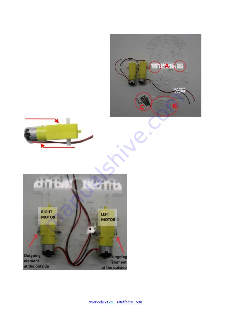
Figure 1 – 3
:
(A)
Location of the grooves where the acrylic
supports of the motors must be inserted
(B)
Motors Acrylic supports
(C)
Screws and nuts to fix motors to the supports
Figure 1 – 4
: Pay attention to motors details
in order to place them in the correct position
Figure 1- 5
:
Motors Installation.
View from the bottom
part of chassis (motor side)
Mark the cables of each motor.
The red cable is always
on the upper part.
Outgoing element
It is recommended to fix the cable with a
hot melt adhesive
Summary of Contents for C-9877
Page 2: ...C 9877 www cebekit es sat fadisel com ...
Page 13: ...C 9877 Figure 2 4 Main control circuit fixed with screws ...
Page 16: ...C 9877 Figure 4 2 Spacers location Figure 4 3 Acrylic board fixing ...
Page 19: ...C 9877 Figure 5 2 Spacers positions Figure 5 3 Control Circuit once fixed ...
Page 36: ...C 9877 Diagram of the control board ...


