background image

______________________________________________________________________________________

Sect. 8) Troubleshooting

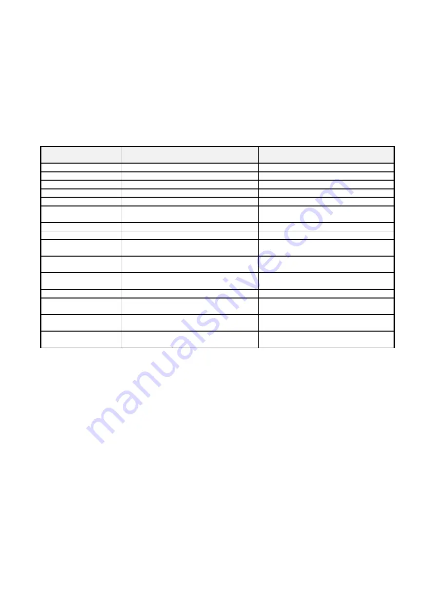
When running a cycle the controller may signal one of the errors listed in the table below.

ERROR CODE 

DISPLAYED

CAUSE 

SOLUTION 

ER21

Hardware fault

Contact the installer.

ER22

Reserved

Contact the installer.

ER23

Reserved.

Contact the installer.

ER24

Reserved.

Contact the installer..

ER25

Cycle in the memory with incorrect data. Program the cycle.

ER26

Attempted running of a cycle without any 
steps being programmed.

Program the cycle.

ER28

Reserved.

Contact the installer.

ER31

Hardware fault.

Contact the installer.

ER41, ER42

Thermocouple continuity failure, not 
connected or connected incorrectly.

Check the thermocouple and 
connections.

ER43

Cold junction temperature sensor broken 
or continuity failure.

Contact the installer.

EREC

Interrupted cycle recovery not initiated 
(kiln temperature outside of set limit).

Run the cycle again.

ERAL

Reserved.

Contact the installer.

EAFS

Cycle stopped due to maximum end 

step wait time (if programmed).

Check the heating elements or reduce 

the kiln charge.

ALL1

Temperature signal outside of maximum 

set limit. (See alarm relay).

Check the heating elements.

ALL2

Activation of alarm configured by 

installer 

Contact the installer.

______________________________________________________________________________________

10

Summary of Contents for MicroProgel TC 32

Page 1: ...ammarby Fabriksv g 43 S 120 33 STOCKHOLM Tel 46 8 658 50 04 Fax 46 8 669 60 98 G teborg Argongatan 8 S 431 53 M LNDAL Tel 46 31 87 51 30 Fax 46 31 87 97 61 Web www cebex se Mail Info cebex se Manual M...

Page 2: ...user PERS and 9 pre configured FIX cycles 6 Sect 4 Entering or modifying the selected cycle 6 Sect 5 Running a cycle 8 Sect 6 Activating the timer for the delayed running of the cycle 8 Sect 7 Settin...

Page 3: ...cycle belongs to the user group customisable The FIX light indicates that the cycle belongs to the group of cycles pre configured by the installer Display STEP of the step in progress If the controll...

Page 4: ...G and STEP displays indicate the cycle and step in progress The group of lights indicate whether in the current step the temperature is increasing heating stabilising or decreasing cooling The energy...

Page 5: ...e the last time the counter was reset by the user the kWh light is on In START mode Normally the controller displays the temperature of the kiln in C on the MAIN display and the C light is on Pressing...

Page 6: ...ep flashing If the cycle is empty that is has not yet been entered the time shown will be 00 00 otherwise the previously set time in hours minutes will be displayed e g 02 25 indicates a time of 2 hou...

Page 7: ...layed is 01 00 that is 1h flashing press En te r the controller prompts the setpoint for the first time setpoint pair STEP no 1 press to increase the value displayed or to decrease it until the temper...

Page 8: ...d to display the following values in sequence Operating setpoint Time elapsed since the start Partial energy consumed since the last start Total energy consumed this value can be reset see the corresp...

Page 9: ...ing for the end of the delay time by pressing the S T O P S T A R T button The time displayed can be increased or decreased using the and buttons WARNING changes made in this way to the start delay ti...

Page 10: ...er ER31 Hardware fault Contact the installer ER41 ER42 Thermocouple continuity failure not connected or connected incorrectly Check the thermocouple and connections ER43 Cold junction temperature sens...

Reviews: