


10
The selection changes each time the button is pressed.
The LEDs light alongside the various symbols to display
your choice.
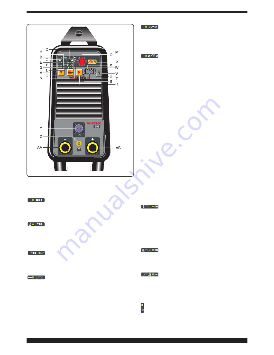
B - LED. MMA welding (Manual Metal Arc)
This machine can weld all types of covered electrodes*
except for cellulosic.In this position, only the knob
O
is
enabled, to adjust the welding current.
C - LED. TIG welding with arc started with-
out high frequency.
To light the arc, press the torch trigger and touch the
tungsten electrode to the workpiece, then lift it. This
move must be quick and decisive.
D - LED. TIG welding with arc started with
high frequency.
To light the arc, press the torch trigger: a high voltage/fre-
quency pilot spark will light the arc.
E - LED. Continuous 2-stage TIG welding
(manual).
When the torch trigger is pressed, the current begins to
increase over the previously set "slope up" time, until it
reaches the value set by means of the knob
O
. When the
trigger is released, the current begins to drop over the
previously set "SLOPE DOWN" time, until it returns to
zero.
In this position, you may connect the pedal control
accessory ART. 193.
F - LED. Continuous 4-stage TIG welding
(automatic).
This program differs from the previous one in that the arc
is both started and shut off by pressing and releasing the
torch trigger.
G - LED. Continuous TIG welding with dual
current level - 4 stages (automatic).
Set the two current levels before lighting the arc:
First level: press the
R
key until the LED
X
lights, and
adjust the main current using the knob
O
.
Second level: press the
R
key until the LED
W
lights, and
adjust the main current using the knob
O
.
When the torch trigger is pressed, the current begins to
increase over the previously set "slope up" time (led S lit),
until it reaches the value set by means of the knob
O
. The
LED
X
lights and appears on the display
P
.
Should it be necessary to reduce the current during weld-
ing, without shutting of the arc (for instance when chang-
ing the welding material or working position, moving from
horizontal to upright, etc.…), press and immediately
release the torch trigger: the current will switch to the
second value selected, the LED W will light and
X
will go
off.
To return to the previous main current, press and release
the torch trigger once again. The LED
X
will light, and the
LED
W
will go off. To stop welding at any time, simply
hold down the torch trigger for more than 0.7 seconds,
then release. The current begins to fall to zero within the
previously set "slope down" time interval (LED
U
lit).
If you press and immediately release the torch trigger dur-
ing the "slope down" phase, you will return to "slope up"
if it is set to greater than zero, or to the lesser current
value of those set.
NOTE: The expression "PRESS AND IMMEDIATELY
RELEASE" refers to a maximum time of 0.5 seconds.
H - LED. Pulsed 2-stage TIG welding (manual).
From a pulse frequency of 0.16 to 1.1Hz, the display
P
alternately shows the peak (main) current and the base
current. The LEDs
X
and
W
light alternately; beyond
1.1Hz the display
P
shows the mean of the two currents,
and the LEDs
X
and
W
both remain lit.
In this position, you may connect the pedal control
accessory ART. 193.
I - LED. Pulsed 4-stage TIG welding
(automatic).
This program differs from the previous one in that the arc
is both started and shut off by pressing and releasing the
torch trigger.
L - LED. Pulsed TIG welding with dual cur-
rent level - 4 stages (automatic).
The welding mode is the same as described for LED
G
.
After adjusting the peak and base currents for the first
level, the relationship between the two will also be upheld
in the second level.
M - LED - THERMAL PROTECTION
Lights when the operator exceeds the duty cycle or
percentage intermittence admissible for the machine,
and simultaneously blocks the current output.
NOTE:
In this condition the fan continues cooling the
power source.
Summary of Contents for BI-WELDER TIG 2040 DC-HF
Page 8: ...72 Art 265...
Page 10: ...74 Art 265...


