


11
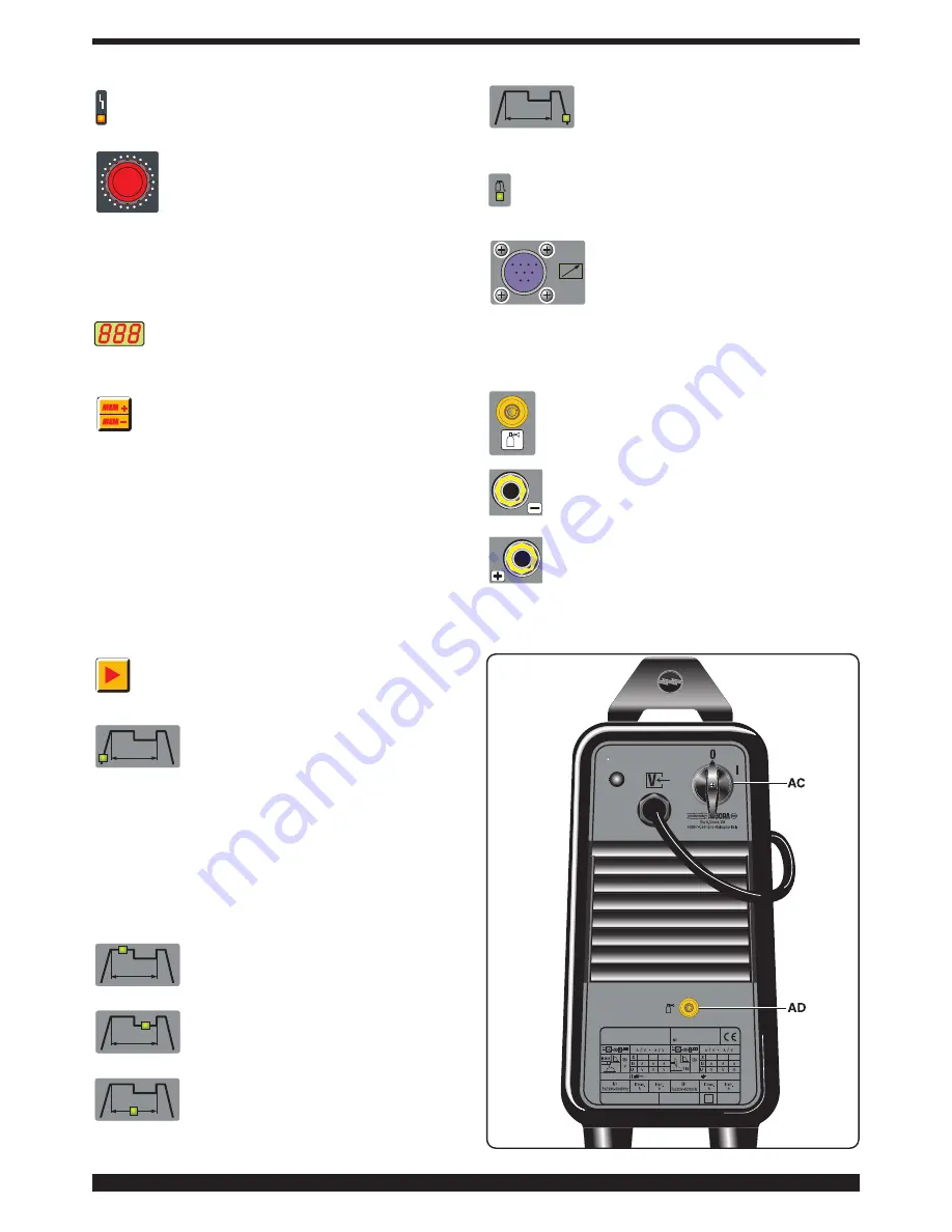
N - BLOCK LED (see 2.3.2)
O - KNOB
Adjusts the welding current.
Also, in combination with the push-button
R
,
you may:
- adjust the second level of current W
-adjust the "slope up"
S
-adjust the "slope down"
U
- adjust the pulse frequency
T
-adjust the post gas
V
P - Display
It shows the welding current and the settings
selected with the button
R
and adjusted with the knob
O
,
as well as the block messages
E1
and
E2
.
Q - SELECTOR
Selects and saves programs.
The welding machine can save nine welding programs
P01…..P09, and call them up using this button.
A
work-
ing program
PL
is also available.
Selecting
When this push-button is pressed briefly, the display
P
shows the next program number after the one being
worked on. If it has not been saved the message will
flash, otherwise it will remain steady.
Saving
Once the program has been selected, hold for more than
3 seconds to save the data. In confirmation, the program
number on the display P will stop flashing
R - SELECTOR
When this button is pressed, the LEDs light in suc-
cession:
S - LED
Slope up. This is the time in which the cur-
rent, starting from the minimum, reaches
the set current value. (0-10 sec.)
Warning
: only those LEDs that refer to the chosen weld-
ing mode will light; i.e., in continuous TIG welding the LED
T
, representing the pulse frequency, will not light.
Each LED indicates the parameter that may be adjusted
by means of the knob
O
while the LED itself is lit. Five
seconds after the last variation, the LED involved will shut
off; the main welding current will be displayed, and the
corresponding LED
X
lights.
X - LED
Main welding current.
W - LED
Second level of welding or base current.
This current is always a percentage of the
main current.
T - LED
Pulse frequency (0.16-250 Hz)
The peak and base times are equal
U - LED
Slope down. This is the time in which the
current reaches the minimum value and the
arc shuts off. (0-10 sec.)
V - LED
Post gas. Adjusts the time gas flows after welding
ends. (0-30 sec.)
Y - 10-PIN CONNECTOR
The following remote controls are con-
nected to this connector:
a) foot control
b) torch with start button
c) torch with potentiometer
d) torch with up/down, etc…
Between pin 3 and 6 the “ARC ON” function is available
(clean contact 1A - 30V).
Z - 1/4 GAS FITTING
This is where the gas hose of the TIG welding
torch is to be connected.
AA
- Negative output terminal (-)
AB
-Positive output terminal (+)
Summary of Contents for BI-WELDER TIG 2040 DC-HF
Page 8: ...72 Art 265...
Page 10: ...74 Art 265...


