background image

CEBORA S.p.A.


10


3.300.160-F 

10-03-2016 

GB 

IMPORTANT

BEFORE 

STARTING 

THE 

EQUIPMENT,  READ  THE  CONTENTS  OF  THIS 
MANUAL, WHICH MUST BE STORED IN A PLACE 
FAMILIAR  TO  ALL  USERS  FOR  THE  ENTIRE 
OPERATIVE  LIFE-SPAN  OF  THE  MACHINE.  THIS 
EQUIPMENT  MUST  BE  USED  SOLELY  FOR 
WELDING OPERATIONS. 
 

1


SAFETY PRECAUTIONS. 

WELDING 

AND 

ARC 

CUTTING 

CAN 

BE 

HARMFUL  TO  YOURSELF 
AND OTHERS. 

• 

The  user  must  therefore  be 

educated  against  the  hazards,  summarized  below, 
deriving  from  welding  operations.  For  more  detailed 
information, order the manual code 3.300.758. 
ELECTRIC SHOCK - May be fatal. 

  Install  and  earth  the  welding  machine 

according to the applicable regulations. 

  Do  not  touch  live  electrical  parts  or 

electrodes  with  bare  skin,  gloves  or  wet 

clothing. 

  Isolate  yourselves  from  both  the  earth  and  the 

workpiece. 

 Make sure your working position is safe. 

FUMES  AND  GASES  -  May  be  hazardous  to  your 

health. 

 Keep your head away from fumes. 

  Work  in  the  presence  of  adequate 

ventilation, and use ventilators around the arc 

to prevent gases from forming in the work area. 
ARC RAYS - May injure the eyes and burn the skin. 

 Protect your eyes with welding masks fitted 

with  filtered  lenses,  and  protect  your  body 
with appropriate safety garments. 

  Protect  others  by  installing  adequate  shields  or 

curtains. 
RISK OF FIRE AND BURNS. 

 Sparks (splatters) may cause fires and burn 

the  skin;  you  should  therefore  make  sure 
there are no flammable materials in the area, 
and wear appropriate protective garments. 

NOISE. 

  This  machine  does  not  directly  produce 

noise 

exceeding 

80dB. 

The 

plasma 

cutting/welding  procedure  may  produce 

noise  levels  beyond  said  limit;  users  must  therefore 
implement all precautions required by law. 
ELECTRIC  AND  MAGNETIC  FIELDS  -  May  be 

dangerous. 

• 

Electric  current  following  through  any 

conductor  causes  localized  Electric  and 
Magnetic Fields (EMF). Welding/cutting 
current creates EMF fields around cables 

and power sources. 

  The  magnetic  fields  created  by  high  currents  may 

affect  the  operation  of  pacemakers.  Wearers  of  vital 
electronic  equipment  (pacemakers)  shall  consult  their 
physician  before  beginning  any  arc  welding,  cutting, 
gouging or spot welding operations. 

  Exposure  to  EMF  fields  in  welding/cutting  may  have 

other health effects which are now not known. 

• 

All  operators  should  use  the  followingprocedures  in 

order  to  minimize  exposure  to  EMF  fields  from  the 
welding/cutting circuit: 

-  Route  the  electrode  and  work  cables  together  – 
Secure them with tape when possible. 
-  Never  coil  the  electrode/torch  lead  around  your 
body. 
-  Do  not  place  your  body  between  the 
electrode/torch  lead  and  work  cables.  If  the 
electrode/torch  lead  cable  is  on  your  right  side,  the 
work cable should also be on your right side. 
-  Connect  the work  cable  to  the  workpiece as  close 
as possible to the area being welded/cut. 
- Do not work next to welding/cutting power source. 

EXPLOSIONS. 

  Do  not  weld  in  the  vicinity  of  containers 

under  pressure,  or  in  the  presence  of 
explosive dust, gases or fumes. 
•  All  cylinders  and  pressure  regulators  used 

in welding operations should be handled with care. 
ELECTROMAGNETIC COMPATIBILITY. 
This  machine  is  manufactured  in  compliance  with  the 
instructions  contained  in  the  harmonized  standard  IEC 
60974-10  (CL.A), 

and  must  be  used  solely  for 

professional  purposes  in  an  industrial  environment. 
There  may  be  potential  difficulties  in  ensuring 
electromagnetic  compatibility  in  non-industrial 
environments. 

DISPOSAL  OF  ELECTRICAL  AND  ELECTRONIC 
EQUIPMENT. 

  Do  not  dispose  of  electrical  equipment 

together with normal waste! 

  In  observance  of  European  Directive 

2002/96/EC 

on 

Waste 

Electrical 

and 

Electronic Equipment and its implementation 

in  accordance  with  national  law,  electrical  equipment 
that  has  reached  the  end  of  its  life  must  be  collected 
separately  and  returned  to  an  environmentally 
compatible  recycling  facility.  As  the  owner  of  the 
equipment,  you  should  get  information  on  approved 
collection  systems  from  our  local  representative.  By 
applying  this  European  Directive  you  will  improve  the 
environment and human health! 


IN 

CASE 

OF 

MALFUNCTIONS, 

REQUEST 

ASSISTANCE FROM QUALIFIED PERSONNEL


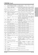
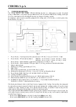
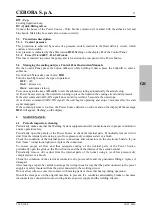
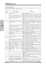
Summary of Contents for MIG 5040/T

Page 1: ...ts 287 AND 289 IN ROBOT APPLICATIONS page 10 E MANUAL DE ISTRUCCIONES PARA GENERADORES Artt 287 Y 289 EN APPLICACIONES ROBOT pag 18 D BETRIEBSANLEITUNG FÜR DIE STROMQUELLEN Art 287 UND 289 IN ROBOTERANWENDUNGEN seite 26 Parti di ricambio e schemi elettrici Spare parts and wiring diagrams page 35 Piezas de repuesto y esquemas electricos Ersatzteile und Schaltpläne ...

Page 2: ...cemaker I portatori di apparecchiature elettroniche vitali pacemaker devono consultare il medico prima di avvicinarsi alle operazioni di saldatura ad arco di taglio scriccatura o di saldatura a punti L esposizione ai campi elettromagnetici della saldatura o del taglio potrebbe avere effetti sconosciuti sulla salute Ogni operatore per ridurre i rischi derivanti dall esposizione ai campi elettromagn...

Page 3: ... 1935 00 l 1 6 m art 1935 01 per Marathon Pack 21 Generatore MIG 3840 T art 287 80 MIG 5040 T art 289 80 22 Gruppo di Raffreddamento GR54 o GR52 24 Pannello di Controllo del Generatore versione completa art 208 00 versione ridotta art 208 10 25 Interfaccia Robot RDI 210 art 210 RAI 211 art 211 RAI 217 art 217 26 Per RDI210 cavo DeviceNet cod 5585987 l 2 m incluso nell Interfaccia Robot Per RAI211 ...

Page 4: ... 8 mediante la prolunga 2 NOTA evitare di disporre la prolunga sotto forma di bobina per ridurre al minimo gli effetti induttivi che potrebbero influenzare il risultati in saldatura MIG MAG pulsato Montare la spina sul cavo d alimentazione facendo particolare attenzione a collegare il conduttore giallo verde al polo di terra Verificare che la tensione d alimentazione corrisponda a quella nominale ...

Page 5: ...atricola da citare per ogni richiesta relativa al Generatore Convertitore statico di frequenza trifase Trasformatore raddrizzatore MIG Adatto per saldatura MIG MAG MMA Adatto per saldatura con elettrodi rivestiti TIG Adatto per saldatura TIG U0 Tensione a vuoto secondaria X Fattore di servizio percentuale Il fattore di servizio esprime la percentuale di 10 minuti in cui il Generatore può lavorare ...

Page 6: ...ot BV Cavo di alimentazione BY Connettore Collegare il connettore del cavo 1 per collegamento Generatore Pannello di Controllo BZ Connettore Collegare il connettore del cavo 3 per collegamento Generatore Interfaccia Robot 5 GRUPPO DI RAFFREDDAMENTO Il Gruppo di Raffreddamento è stato progettato per raffreddare le torce utilizzate per la saldatura Deve essere utilizzato esclusivamente con i generat...

Page 7: ...gnale di start Se la pressione del liquido refrigerante è insufficiente il Generatore non eroga corrente e sul display O compare la scritta H2O lampeggiante 6 MANUTENZIONE 6 1 Ispezione periodica pulizia Periodicamente controllare che le apparecchiature del Sistema di Saldatura e tutti i collegamenti siano in condizione di garantire la sicurezza dell operatore Periodicamente aprire i pannelli del ...

Page 8: ...Precarica e Controllo Sostituire schede Precarica e Controllo 14 Errore della tensione di alimentazione del Microprocessore su scheda Micro Controllare cablaggio fra schede Micro e Flyback Sostituire schede Controllo e o Flyback 15 solo 289 Tensione continua all uscita della scheda Precarica inferiore al valore previsto Controllare condizioni della tensione di rete Verificare che Ponte Raddrizzato...

Page 9: ...lo 62 solo 289 Fase LI della tensione di rete superiore al valore massimo consentito Verificare il valore delle tre fasi della tensione di rete Sostituire schede Precarica e o Controllo 63 solo 289 Fase L2 della tensione di rete inferiore al valore minimo consentito Verificare il valore delle tre fasi della tensione di rete Sostituire schede Precarica e o Controllo 64 solo 289 Fase L2 della tensio...

Page 10: ...rrents may affect the operation of pacemakers Wearers of vital electronic equipment pacemakers shall consult their physician before beginning any arc welding cutting gouging or spot welding operations Exposure to EMF fields in welding cutting may have other health effects which are now not known All operators should use the followingprocedures in order to minimize exposure to EMF fields from the w...

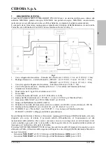
Page 11: ...ding wire sheath art 1935 00 l 1 6 m art 1935 01 per Marathon Pack 21 Power Source MIG 3840 T art 287 80 MIG 5040 T art 289 80 22 Cooling unit GR54 o GR52 24 Power Source Control Panel full version art 208 00 light version 208 10 25 Robot Interface RDI 210 art 210 RAI 211 art 211 RAI 217 art 217 26 For RDI210 cable DeviceNet cod 5585987 l 2 m included in Robot Interface For RAI211 e RAI217 dedicat...

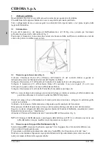
Page 12: ...ce 21 to the Wire Feeder 8 by means of the extension 2 NOTE avoid coiling the connection to reduce to a minimum the inductive effects that could affect the results in pulsed MIG MAG welding Mount the plug on the power cord being especially carefully to connect the yellow green conductor to the earth pole Make sure that the supply voltage corresponds to the rated voltage of the Power Source Size th...

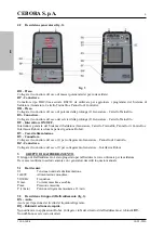
Page 13: ...99 N Serial number Must be indicated on any request regarding the Power Source Three phase static frequency converter Transformer rectifier MIG Suitable for MIG MAG welding MMA Suitable for welding with covered electrodes TIG Suitable for TIG welding U0 Secondary open circuit voltage X Duty cycle percentage The duty cycle expresses the percentage of 10 minutes during which the Power Source may run...

Page 14: ...obot management part BV Power cord BY Connector Connect the connector of the cable 1 to connect the Power Source Control Panel BZ Connector Connect the connector of the cable 3 to connect the Power Source Robot Interface 5 COOLING UNIT The Cooling Unit was designed to cool the torches used for welding It must be used exclusively with the Power Sources described in this manual 5 1 Technical specifi...

Page 15: ...he coolant pressure is too low the Power Source delivers no current and on the display O the message H2O will appear flashing on the display 6 MAINTENANCE 6 1 Periodic inspection cleaning Periodically make sure that the Welding System equipment and all connections are in proper condition to ensure operator safety Periodically open the panels of the Power Source to check the internal parts Periodic...

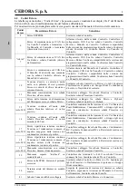
Page 16: ...back boards Replace Control and or Flyback boards 15 only 289 Precharge board output DC voltage lower than preview value Check mains voltage conditions Make sure Rectifier Bridge DC capacitors or Igbt Group are not in short circuit Replace Precharge and or Control boards 16 Precharge board output DC voltage lower than allowed minimum value 400 Vdc Check mains voltage conditions Make sure Rectifier...

Page 17: ...ins three phases values Replace Precharge and or Control boards 63 only 289 L2 Mains Phase voltage lower than minimum allowed value Make sure the mains three phases values Replace Precharge and or Control boards 64 only 289 L2 Mains Phase voltage higher than maximum allowed value Make sure the mains three phases values Replace Precharge and or Control boards 65 only 289 L3 Mains Phase voltage lowe...

Page 18: ...itales pacemaker deben consultar el médico antes de acercarse a las operaciones de soldadura de arco de corte desagrietamiento o de soldadura por puntos La exposición a los campos electromagnéticos de la soldadura o del corte podrían tener efectos desconocidos sobre la salud Cada operador para reducir los riesgos derivados de la exposición a los campos electromagnéticos tiene que atenerse a los si...

Page 19: ...5 00 l 1 6 m art 1935 01 per Marathon Pack 21 Generador MIG 3840 T art 287 80 MIG 5040 T art 289 80 22 Grupo de Enfriamiento GR54 o GR52 24 Panel de Control del Generador versión completa art 208 00 versión reducida art 208 10 25 Interfaz Robot RDI 210 art 210 RAI 211 art 211 RAI 217 art 217 26 Para RDI210 cable DeviceNet cod 5585987 l 2 m incluso en la Interfaz Robot Para RAI211 y RAI217 cablaje ...

Page 20: ...le de prolongación 2 NOTA evitar de disponer el cable de prolongación bajo forma de bobina para reducir al mínimo los efectos inductivos que podrían influenciar el resultado en la soldadura MIG MAG pulsado Montar el enchufe en el cable de alimentación teniendo particular cuidado de conectar el conductor amarillo verde al polo de tierra Verificar que la tensión de alimentación corresponda a la nomi...

Page 21: ...o de matrícula que se citará en todas las peticiones relativas al Generador Convertidor estático de frecuencia trifásica Transformador rectificador MIG Adapto a la soldadura MIG MAG MMA Adapto a la soldadura con electrodos revestidos TIG Adapto a la soldadura TIG U0 Tensión en vacío secundaria X Factor de servicio porcentaje El factor de servicio expresa el porcentaje de 10 minutos en el que el Ge...

Page 22: ...arte de gestión Robot BV Cable de alimentación BY Conector Conectar el conector del cable 1 para conexión Generador Panel de Control BZ Conector Conectar el conector del cable 3 para conexión Generador Interfaz Robot 5 GRUPO DE ENFRIAMIENTO El Grupo de Enfriamiento ha sido proyectado para enfriar las antorchas utilizadas para la soldadura Deberá ser utilizado exclusivamente con los generadores des...

Page 23: ...n periódica limpieza Periódicamente controlar que los dispositivos del Sistema de Soldadura y todas las conexiones sean capaces de garantizar la seguridad del operador Periódicamente abrir los paneles del Generador y controlar los elementos internos Eliminar la eventual suciedad o polvo de los elementos internos utilizando un chorro de aire comprimido seco a baja presión o un pincel Controlar las ...

Page 24: ...rjetas Control y o Flyback 15 solo 289 Tension continua a la salida de la tarjeta Precarga inferior al valor previsto Controlar las condiciones de la tension de red Verificar que el Puente Rectificador los Condensadores DC o el Grupo Igbt no sean en cortocircuito Substituir las tarjetas Precarga y o Control 16 Tension continua a la salida de la tarjeta Precarga inferior al valor minimo 400 Vdc Con...

Page 25: ... 289 Fase L1 de la tension de red superior del valor massimo concurrido Verificar el valor de las tres fases de la tension de red Substituir las tarjetas Precarga y o Control 63 solo 289 Fase L2 de la tension de red inferior del valor mínimo concurrido Verificar el valor de las tres fases de la tension de red Substituir las tarjetas Precarga y o Control 64 solo 289 Fase L2 de la tension de red sup...

Page 26: ...elder können den Betrieb von Herzschrittmachern stören Träger von lebenswichtigen elektronischen Geräten Herzschrittmacher müssen daher ihren Arzt befragen bevor sie sich in die Nähe von Lichtbogenschweiß Schneid Brennputz oder Punktschweißprozessen begeben Die Aussetzung an die beim Schweißen oder Schneiden erzeugten elektromagnetischen Felder kann bislang unbekannte Auswirkungen auf die Gesundhe...

Page 27: ... L 1 6 m Art 1935 01 für Marathon Pack 21 Stromquelle MIG 3840 T Art 287 80 MIG 5040 T Art 289 80 22 Kühlaggregat GR54 oder GR52 24 Steuertafel der Stromquelle komplette Version Art 208 00 reduzierte Version Art 208 10 25 Roboterschnittstelle RDI 210 Art 210 RAI 211 Art 211 RAI 217 Art 217 26 Für RDI210 DeviceNet Kabel Bestellnr 5585987 L 2 m im Lieferumfang der Roboterschnittstelle enthalten Für ...

Page 28: ...en ANMERKUNG Beim Verlegen der Zwischenverbindung darauf achten dass sich keine Spirale bildet um induktive Störungen beim MIG MAG Impulslichtbogenschweißen zu vermeiden Den Netzstecker auf das Netzkabel montieren Hierbei ist unbedingt zu beachten dass der gelb grüne Schutzleiter an den Schutzkontakt angeschlossen werden muss Sicherstellen dass die Netzspannung der Nennspannung der Stromquelle ent...

Page 29: ...99 N Seriennummer sie muss bei allen Anfragen zur Stromquelle stets angegeben werden Statischer Dreiphasen Frequenzumrichter Transformator Gleichrichter MIG Geeignet zum MIG MAG Schweißen MMA Geeignet zum Schweißen mit umhüllten Elektroden TIG Geeignet zum WIG Schweißen U0 Leerlauf Sekundärspannung X Relative Einschaltdauer Die relative Einschaltdauer ist der auf eine Einschaltdauer von 10 Minuten...

Page 30: ...euerung BV Netzkabel BY Steckverbinder Den Steckverbinder des Kabels 1 für die Verbindung Stromquelle Steuertafel anschließen BZ Steckverbinder Den Steckverbinder des Kabels 3 für die Verbindung Stromquelle Roboterschnittstelle anschließen 5 KÜHLAGGREGAT Das Kühlaggregat dient zum Kühlen der zum Schweißen verwendeten Brenner Es darf nur mit den in dieser Betriebsanleitung beschriebenen Stromquelle...

Page 31: ...d ist gibt die Stromquelle keinen Strom ab und auf dem Display O erscheint die blinkende Anzeige H2O 6 WARTUNG 6 1 Regelmäßige Inspektion Reinigung In regelmäßigen Zeitabständen kontrollieren ob sich das Schweißsystem und alle Verbindungen in einem Zustand befinden der die Sicherheit des Benutzers garantiert Die Stromquelle in regelmäßigen Zeitabständen öffnen und ihre internen Komponenten kontrol...

Page 32: ...e und oder die Driver Platine und oder die IGBT Platine auswechseln Den Haupttrafo und oder die Diodengruppe und oder die Ausgangsdrossel und oder den Strommessumformer auswechseln 13 Keine Kommunikation mit der Vorladeplatine beim Einschalten Verdrahtung zwischen der Vorladeplatine und der Steuerplatine kontrollieren Die Vorladeplatine und die Steuerplatine auswechseln 14 Fehler bei der Versorgun...

Page 33: ...mverdrahtung zwischen dem Ausgang der Diodengruppe und den Ausgangsanschlüssen der Stromquelle kontrollieren Die Steuerplatine und oder den Strommessumformer auswechseln 56 Zeitüberschreitung zu lange Dauer des Kurzschlusses Den Verschleißzustand des Brenners und die Hauptstromverdrahtung zwischen dem Ausgang der Diodengruppe und den Ausgangsanschlüssen der Stromquelle kontrollieren Die Messplatin...

Page 34: ...er oder Roboter ausgeschaltet Die Verbindungen zwischen der Stromquelle und dem Roboter die Stromversorgung des Roboters und oder die Sicherheitsbedingungen der Anlage kontrollieren Sti 91 Draht verklebt Den Draht abschneiden oder die Prozedur Automatisches Lösen des Drahts ausführen siehe die Betriebsanleitung der Roboterschnittstelle End 92 Draht zu Ende Die Drahtspule auswechseln Ito 98 Der Lic...

Page 35: ...CEBORA S p A 35 3 300 160 F 10 03 2016 Art 287 80 ...

Page 36: ...bio deve indicare sempre numero di articolo matricola e data di acquisto della macchina posizione e quantità del ricambio Art 287 80 N Descrizione Description 538 Pannello anteriore Front panel 539 Circuito flyback Flyback circuit 540 Autotrasformatore Autotransformer 541 Piano intermedio Inside baffle 542 Circuito filtro Filter circuit 543 Circuito di controllo Control circuit 544 Condensatore Ca...

Page 37: ...CEBORA S p A 37 3 300 160 F 10 03 2016 Art 289 80 ...

Page 38: ...zzi di ricambio deve indicare sempre numero di articolo matricola e data di acquisto della macchina posizione e quantità del ricambio Art 289 80 N Descrizione Description 291 condensatore Capacitor 292 Circuito driver Driver circuit 293 Igbt Igbt 294 Isolamento Insulation 295 Kit igbt driver isol Igbt driver insul Kit 296 Resistenza Resistor 297 Cavallotto Jumper 298 Isolamento Insulation 299 Cava...

Page 39: ...CEBORA S p A 39 3 300 160 F 10 03 2016 ...

Page 40: ...CEBORA S p A 40 3 300 160 F 10 03 2016 GR 52 ...

Page 41: ... position and the quantity GR 52 N Descrizione Description 10 Laterale destro Right side panel 11 Fondo gruppo raffr Cooling unit bottom 12 Appoggio Rest 13 Serbatoio Tank 14 Tappo Cap 15 Pannello anteriore Front panel 16 Cornice Frame 17 Raccordo Fitting 18 Raccordo Fitting 19 Raccordo Fitting 20 Laterale sinistro Left side panel 21 Coperchio Cover 22 Raccordo a tre vie T fitting 23 Raccordo Fitt...

Page 42: ...CEBORA S p A 42 3 300 160 F 10 03 2016 ...

Page 43: ...CEBORA S p A 43 3 300 160 F 10 03 2016 ...
Page 44: ...CEBORA S p A 44 3 300 160 F 10 03 2016 ...

Reviews: