Input and outputs
General
The following points deal with physical and electrical aspects
of Power1401 connectors, rather than their electronic function.
The outer sleeves of the front-panel BNCs, and the metal shells
of the various rear-panel connectors, are robustly connected to
the metalwork of the case and, via the earth pin of the DC inlet
and the earth leads of the power brick, to mains earth. All signal
returns are tied to mains earth on the printed circuit board.
Items of equipment connected to the Power1401 must not be
treated as isolated from mains earth, nor from each other.
Mains earth
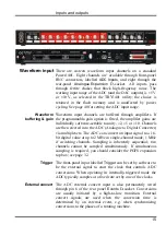
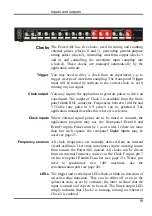
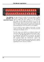
All front-panel BNCs have adjacent yellow LEDs. These flash
or blink to show appropriate activity, e.g. an ADC input LED
lights when its channel is active; a DAC output LED flashes
when its channel is updated; digital output LEDs will light
when their bit is set. LEDs may light to prompt users to make
connections. LEDs flash in a distinctive manner on self test. If
all ADC and DAC LEDs turn on at once, and the pushbutton
LED turns off, the 1401 is overheating. The pushbutton lights
red to indicate self-test, and flashes red and green if a hardware
error has been detected. Normally it glows green, indicating
that none of the internal voltage rails has drifted outside limits.
See also
LED diagnostic patterns
Front-panel LEDs
Chips connected directly to the outside world are susceptible to
damage from electrostatic discharge or signal overload, though
in practice this seems to happen only rarely. In the case of the
ADC inputs and DAC outputs the chips are in sockets, to allow
their replacement without unsoldering. All such chips are
readily-available types; if ordering, specify the exact part-code
as on page 37 to ensure insertion-mount, lead-free parts. See
page 36 for opening the Power1401 and page 37 for the
location and identification of socketed chips.
Socketed chips
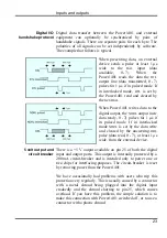
Digital and event input signals pass through low-voltage chips
that are only available in surface-mount style and so cannot be
socketed. These chips are protected by MOSFET devices and
are safe against moderate overvoltages of either polarity.
MOSFET protection
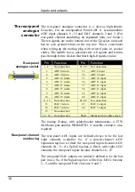
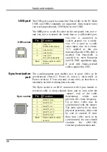
On the following pages, all rear-panel connectors are drawn as
the user sees them, i.e. viewed from the
outside
. This is also the
view of their mating connectors as seen while wiring them up!
Connector diagrams
14
Summary of Contents for Power1401-3
Page 56: ...User notes 50 ...

