Inputs and outputs
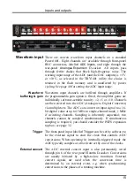
The front-panel waveform input channels each have an
associated yellow LED. They are controlled by software
command and typically turn on when the channel is in use.
ADC LEDs
The trigger-input LED flashes or blinks on detection of an
active-edge transition at the
Trigger
input. The LED can be set
by software to be either on or off during the quiescent state.
Trigger LED
The input impedance of the waveform channels is 1 megohm.
The waveform inputs expect to be driven from a low-
impedance source (100 ohms or less); the output of most
amplifiers is suitable. The maximum non-destructive input
voltage range is ±15 V. If you do overdrive the inputs, it is
possible to damage the input buffer amplifiers. These chips are
in sockets for easy replacement. See page 36 for opening the
Power1401; see page 37 for the precise part number to ensure
lead-free, insertion-mount style.
Technical details:
Analogue input
The front-panel
Trigger
input has a normal working voltage
range of 0 V to +5 V. There is MOSFET circuit protection
allowing a safe input range of
10 V. This input is held
internally to +5 V by a 100 kilohm resistor and has input
hysteresis: the low-going threshold voltage is set at 0·95 V and
the high-going threshold at 1·2 V. Pulses driving the trigger
input should be 1
s or longer. To pull this input low, the
driving device must be able to sink 50
A.
Front-panel
Trigger input
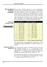
The rear-panel ADC external-convert input is on pin 6 of the
Events
D-socket. It responds to TTL and switch closure signals,
and has a normal working voltage range of 0 V to +5 V. There
is MOSFET circuit protection allowing a safe input range of
10 V. This input is held internally at +5 V via a 10 kilohm
resistor. Input pulses should be at least 1 µs long and must fall
below 0·8
V for guaranteed recognition. Conversion is
normally initiated on the high-to-low edge. Use of the other
edge can be selected by switch; see page 36.
Rear-panel ADC
external convert
input
The ADC input voltage is resolved into 65536 levels (sixteen-
bit precision); each step is approximately 150
V with an input
range of ±5 V or 300
V with an input range of ±10 V.
The ADC
16
Summary of Contents for Power1401-3
Page 56: ...User notes 50 ...

