Inputs and outputs
Waveform output
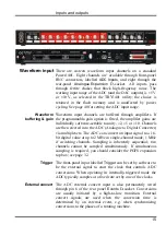
There are four waveform output channels on the Power1401
.
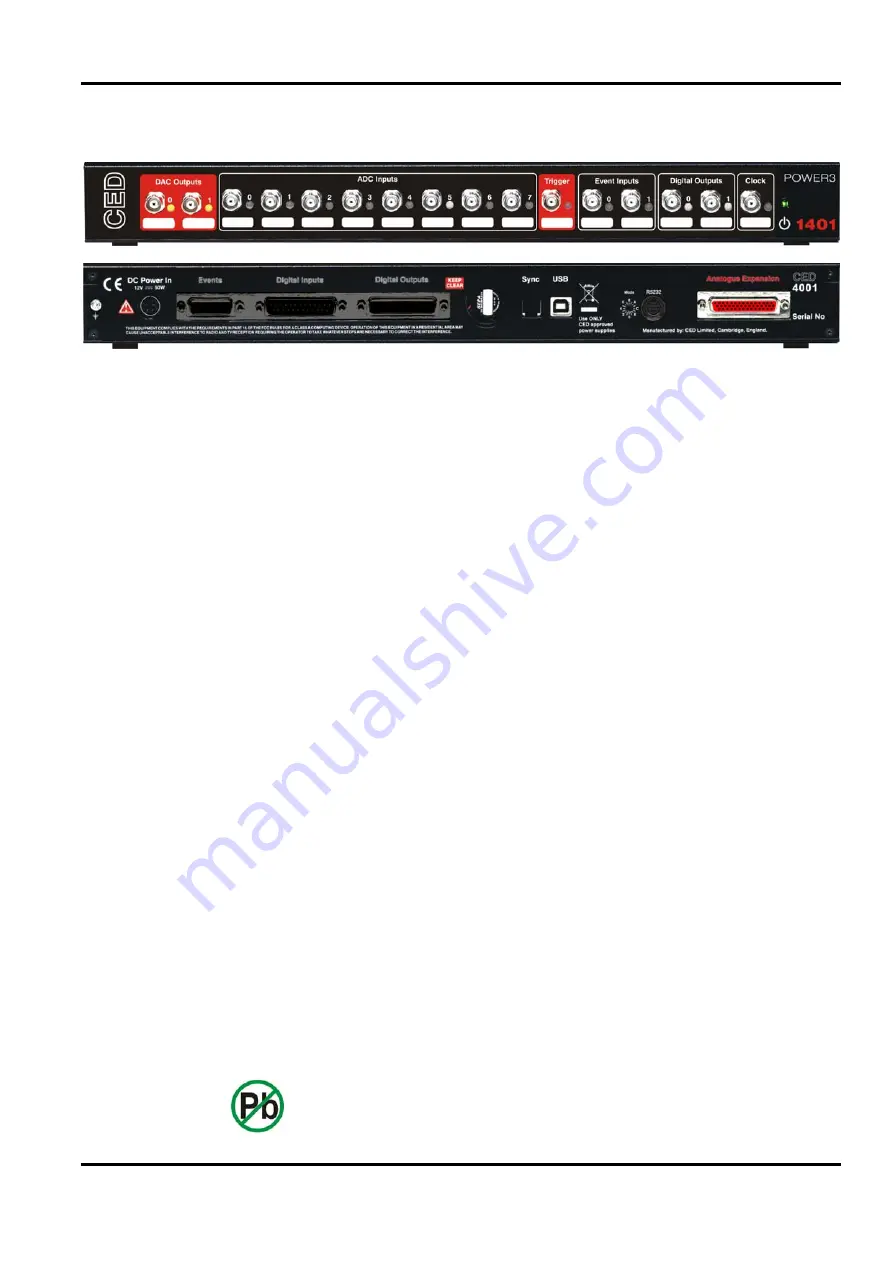
Two are on BNC connectors on the front panel, labelled
DAC Outputs
(Digital to Analogue Converters), and two on the
rear-panel
Analogue Expansion
D-socket
.
All outputs pass
through ferrite chokes that block high-frequency noise.
The DAC waveform outputs generate voltages in the range
±5 V, in steps of approximately 150
V (16-bit precision). The
output range may be changed to ±10 V, and 300
V steps, by
software option. The selected range applies to all four DACs
(and also the ADC inputs). The choice is retained in non-
volatile EEPROM and is unaffected by power cycling. See
page 40 for setting the DAC output range.
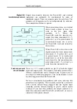
The DACs can be set by program to update in response to an
external signal, either the rear-panel
Event
Clock F input (see
page 21), or the front panel
Trigger
input, so as to synchronize
the update rate with external equipment. Alternatively, they can
be updated at a fixed rate set by one of the internal clocks.
When multiple channels of waveform are output, the
Power1401 can be programmed to update several DACs
simultaneously. The maximum update rate is 500 kHz.
Update modes
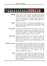
The front-panel DAC output channels each have an associated
yellow LED. The LED is controlled by software and typically
turns on when the channel is in use.
DAC LEDs
The waveform outputs are designed for driving loads of
600 ohms impedance or higher, and are short-circuit proof. For
full accuracy, the load should not be less than 5 kilohms. The
output amplifiers are fitted in sockets for easy replacement. See
page 36 for opening the Power1401; see page 37 for the precise
part number to ensure lead-free, insertion-mount style.
Technical details
17
Summary of Contents for Power1401-3
Page 56: ...User notes 50 ...


