Inputs and outputs
Clocks
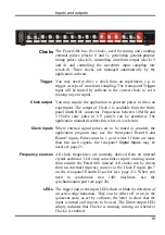
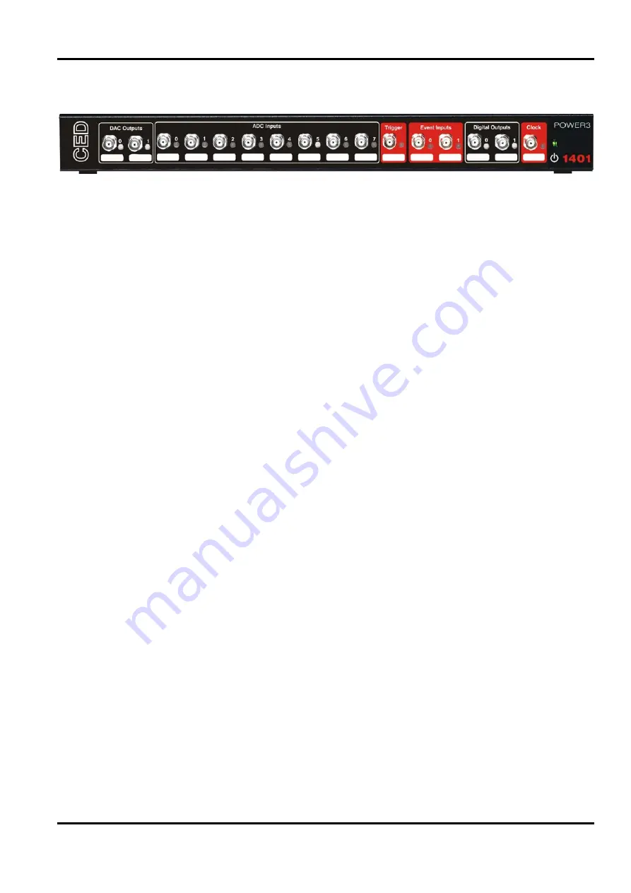
The Power1401 has five clocks, used for timing and counting
external pulses (clocks 0 and 1), generating general-purpose
timing pulses (clock 2), controlling waveform output (clocks 3
and 4) and controlling the waveform input sampling rate
(clock 4). These clocks are managed automatically by the
application software.
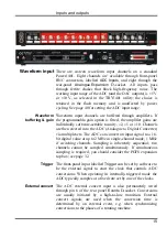
You may need to drive a clock from an experiment, e.g. to
trigger sweeps of waveform sampling. The front-panel
Trigger
input will be routed by software to the correct clock, to set it
running on your signal.
Trigger
You may require the application to generate pulses to drive an
experiment. The output of Clock 2 is available from the front-
panel
Clock
BNC connector. Frequencies between 10 MHz and
3·55 nHz (one pulse in 8·9 years!) can be generated. The
application manual describes this where it is relevant.
Clock output
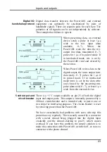
Where external signal pulses are to be timed or counted, the
application program may use the front-panel
Event 0
and
Event 1
inputs. Pulses must be 1
s or wider. If there are more
than two such signals, the rear-panel
Digital Inputs
may be
used; see page 25.
Clock inputs
All clock frequencies are normally derived from an internal
crystal oscillator. Users may sometimes require a timing source
from outside the Power1401 instead. All clocks can be driven
from an external frequency source via the Clock F input, pin 7
on the rear-panel
Events
D-socket (see page 21). When you
need to synchronize two 1401 machines, use the
synchronization port (see page 26).
Frequency sources
The trigger and event-input LEDs flash or blink on detection of
an active-edge transition. They can be either off or on in the
quiescent state, as set by software, the latter to show that the
input is armed and expects to be used. The
Clock
output LED
simply indicates that Clock 2 is running, turning on whenever
Clock 2 is enabled.
LEDs
19
Summary of Contents for Power1401-3
Page 56: ...User notes 50 ...

