Inputs and outputs
The frequency synthesizer is an internal device capable of
generating frequencies that cannot be obtained by simple
integer division of the 25 MHz crystal oscillator. An example of
this would be the 44·1 kHz sampling frequency widely used in
digital audio applications. Two such frequencies can be
generated independently by the frequency synthesizer; the
outputs may be used internally, e.g. to control ADC sampling
rate or DAC update rate, or routed to the Clock 2 output.
Frequency
synthesiser
The frequency synthesizer is not currently (August 2012)
supported in application software.
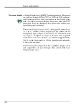
The normal input range of
Trigger
,
Event 0
and
Event 1
is 0 V
to +5 V. There is MOSFET circuit protection allowing a safe
input range of
10 V. These inputs are held internally to +5 V
by 100 kilohm resistors and have input hysteresis: the low-
going threshold voltage is set at 0·95 V and the high-going
threshold at 1·2 V. To pull these inputs low, the driving device
must be able to sink 50
A. Pulses driving these front panel
inputs must be 1
s or wider.
Technical details
Clock
is an output, driven by an SN74HCT244 lead-free,
surface-mount bus driver element which can source or sink
24 mA. Note that, since this is an output device, it cannot have
MOSFET protection. If it is damaged, its replacement will
involve unsoldering and resoldering.
Trigger, Clock 2, Event 0, and Event 1 all pass through ferrite
chokes that block high-frequency noise.
20
Summary of Contents for Power1401-3
Page 56: ...User notes 50 ...


