Inputs and outputs
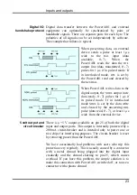
Digital data transfer between the Power1401 and external
equipment can optionally be synchronized by pairs of
handshake signals. There are separate pairs for each byte. The
polarities of all signals can be set independently by software.
The example that follows is typical.
Digital I/O
handshake protocol
When presenting data, an external
device sends a pulse at least 1
s
wide to the
DAL
input (data
available,
0 - 7
)
. When the
Power1401 reads the data the
DTL
output line (data transmitted, 0 - 7
)
pulses for 1 µs if in pulsed mode. If
in interlocked mode,
DTL
is set by
the Power1401 read and cleared by
the next
DAL
.
When Power1401 writes data to the
digital output, the
NDRL
output (new
data ready, 0 - 7) pulses for 1 µs if
in pulsed mode. If in interlocked
mode
NDRL
is set by the data write
and cleared by the answering
DRL
pulse (data read, 0 - 7), at least 1 µs
wide, from the external device.
There is a +5 V output available on pin 25 of both the digital
input and output ports. This output is internally protected by a
200 mA circuit-breaker and is intended only to power one or
two chips for interfacing purposes. The circuit-breaker is reset
by removing power from the Power1401.
5 volt output and
circuit breaker
We have occasionally had problems with users who trip this
protection very regularly. This is usually caused by a connector
with a metal shroud being plugged into the digital input
crookedly and the shroud shorting to pin 25, which causes
overload. If you have this problem, the simple solution is to
make this connection with Power1401 switched off, or to use a
connector with a plastic shroud.
23
Summary of Contents for Power1401-3
Page 56: ...User notes 50 ...


