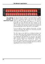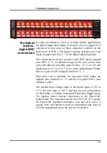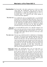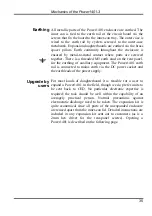
Inputs and outputs
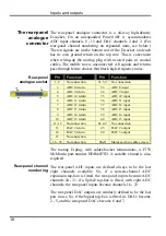
25
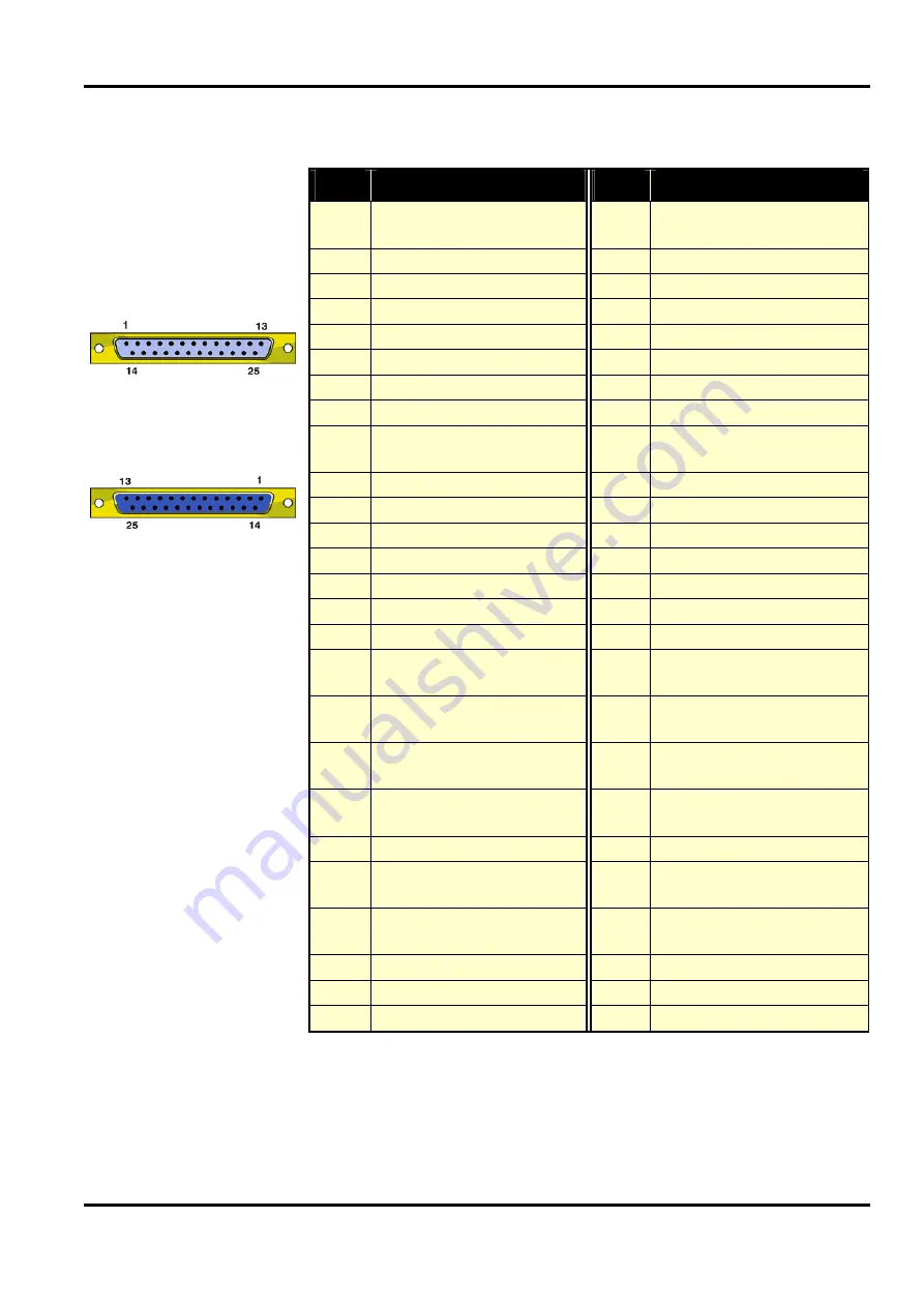
Pin
Output function
Pin
Input function
1
High byte out
Word out
7
15
1
High byte in
Word in
7
15
14 6
14
14 6
14
2
5
13 2
5
13
15 4
12
15 4
12
3
3
11 3
3
11
16 2
10
16 2
10
4
1
9
4
1
9
17 0
8
17 0
8
5
Low byte out
Word out
7
7
5
Low byte in
Word in
7
7
18 6
6
18 6
6
6
5
5
6
5
5
19 4
4
19 4
4
7
3
3
7
3
3
20 2
2
20 2
2
8
1
1
8
1
1
21 0
0
21 0
0
9
DRH
Data received 8-15 i/p
9
DTH
Data transmitted 8-15 o/p
22
User i/p
(buffered, reserved)
22
1-wire port i/o
10
User o/p
(buffered, reserved)
10
Not connected
23
NDRL
New data ready 0-7 o/p
23
DAL
Data available 0-7
i/p
11
Output disable i/p 11
Not connected
24
DRL
Data received 0-7 i/p
24
DTL
Data transmitted 0-7 o/p
12
NDRH
New data ready 8-15 o/p
12
DAH
Data available 8-15 i/p
25 +5V (200mA maximum)
25 +5V (200mA maximum)
13
Ground
13
Ground
Shell Mains earth to cable screen Shell Mains earth to cable screen
Digital I/O
connectors
Digital Input plug
Digital Output socket
The mating connectors, with solder-bucket terminations, are
ITW McMurdo part-numbers DB25P (25-way plug) and
DB25S (25-way socket). Suitable shrouds are also required.
Summary of Contents for Power1401-3
Page 56: ...User notes 50 ...


