Inputs and outputs
USB port
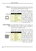
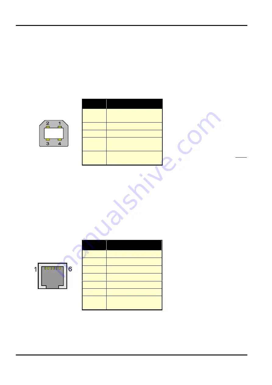
The USB port is used to connect the Power1401 to the PC. Both
USB1 and USB2 standards are supported. Data transfer rates
can reach approximately 38 MBytes/sec for USB2.
The
USB
port is a style B socket on the rear panel.
USB
_
DATA
+
and
USB
_
DATA
- transmit the serial data as a differential pair.
USB
_
GND
is connected to
system ground via a choke.
USB
_+5
V
is used as a cable
sense input, also via a choke;
+5
V applied to this pin
indicates that the USB cable is
inserted. The Power1401 is
specified to meet European
and US EMC regulations only
if used with braid-screened
cables supplied by CED.
Pin
Function
1
USB
+5
V
(USB cable detect)
2
USB
_
DATA
+
3
USB
_
DATA
-
4
USB
_
GND
(to system ground)
Shell
Mains earth to cable
screen
USB socket
Synchronization
port
The synchronization port enables two or more 1401s to be
synchronized (Power-3, Power II, micro-3, micro mk II or
Power serial no. P 3xxx onwards, in any mix), so that there is
absolutely no drift in timing between units.
The
Sync
socket is an RJ12 connector with 6 pins loaded. A
screened cable is daisy-chained from unit to unit, with the
‘master’ end of the cable
determining which unit
provides the clock frequency.
Up to three 1401s may be
synchronized with the master.
The units need to be in close
physical proximity, either side
by side or stacked. If more
than four 1401s need to be
synchronized, the user should
consider the CED
3301
external synchronization unit.
Pin
Function
1
MHZ
20_
TR
x
2
MHZ
20_
IN
3
MHZ
20_
IN
+
4
MHZ
20_
OUT
5
MHZ
20_
OUT
+
6
MHZ
20_
TR
x+
Shell
Mains earth to cable
screen
Sync socket
26
Summary of Contents for Power1401-3
Page 56: ...User notes 50 ...

