Maintenance operations
LED diagnostic
patterns
The self-diagnostic
firmware of the
Power1401-3 can display
a number of patterns on
the front-panel BNC
LEDs and the
indicator. These
indicate normal running,
the phases of self-test,
and various error
conditions.
45
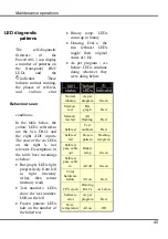
In the table below, the
yellow LEDs referred-to
are the two DACs and
the eight ADC inputs.
The state of the six LEDs
on the right is not
relevant. Descriptions in
the table have meanings
as below:
Bar graph: LEDs light
progressively from left
to right (memory
write), then retreat
(memory read)
Test numbers: LEDs
show the test number,
LSB on the left
Frozen pattern: LEDs
halt on the number of
the failed test
Binary ramp: LEDs
count up in binary
Dancing DACs: the
two leftmost LEDs
toggle their original
states at 1 Hz
As per program / As
before: LEDs continue
doing whatever they
were doing before
1401
status
Yellow
LEDs
Indicator
Normal
running
As per
program
Green
Memory
test
Bar
graph
Red
Memory
test fail
All
flashing
Red
Self-test
Test
numbers
Red
Self-test
fail
Frozen
pattern
Flashing
red/green
Self-test
pass, cable
out
Binary
ramp
Green
Self-test
pass, cable
in
All off
Green
Total
hardware
failure
All on
Red
CPU crash
Dancing
DACs
As before
Software
error
As per
program
Red
Over-
temperature
All on
Off
Behaviour seen
Summary of Contents for Power1401-3
Page 56: ...User notes 50 ...

