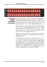
Maintenance
operations
Introduction
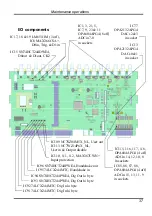
The Power1401 requires very little maintenance. This section
covers simple operations that may occasionally need the case
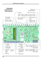
opened, such as setting the internal options switch, replacing
damaged I/O chips, upgrading memory, or re-calibrating the
analogue system. We also describe updating the flash ROM.
Taking the lid off
To open the Power1401, turn the unit off and disconnect the
power lead and any other cables. Unscrew the four M3 screws
at the corners of the rear panel (or panels) with a 2 mm hex
wrench. Do not unscrew the green & yellow earth wire. Slide
out the top cover. Be careful not to splay the sides: the case
loses rigidity once the back is off.
The inner can is now visible. Slide it out to the rear, and unplug
the green & yellow earth wire from the side. It may be quite
tight. Undo the six M3 ‘combi’ screws (with captive shakeproof
washers) using a 1-pt Pozidriv screw-driver. Gently pull the lid
up and off. Note the position of the graphite-impregnated
gasket strips. They are quite delicate, so store them safely. The
circuit board is now ready to be worked on.
To reassemble the Power1401, simply reverse this procedure.
Switch settings
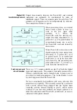
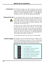
This diagram shows the internal options switch settings on the
Power1401. Logically, On counts as 0, Off as 1. Most options
concern self-test and debug. Normally, all switches must be On,
physically towards the edge of the circuit board, as shown.
36
S W 2
1 = Loop mode on start
1 = Long memory test & test on each pass
1 = Special DigI/O cables fitted
1 = No wait for host handshake on power up
1 = Invert ADC External Convert & Events
1 = Force memory 2T mode in slow DDRs
1 = Show serial line output during test
1 = Continuous self-test
ON 1
2
3
4
5
6
7
8
Summary of Contents for Power1401-3
Page 56: ...User notes 50 ...


