background image

Questions, problems, missing parts? 

Before returning to your retailer, call 

our customer service department at 1-866-573-0674, 8:00 am - 4:30 pm CST, 

Monday through Friday or email

 customerservice@usaprocom.com


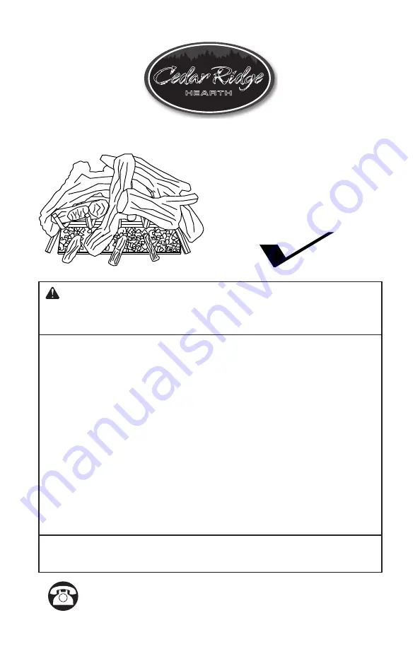
WARNING: If the information in this manual is not 

followed exactly, a fire or explosion may result causing 

property damage, personal injury or loss of life.
—  Do not store or use gasoline or other  flammable va-

pors and liquids in the  vicinity of this or any other 

appliance.

—  WHAT TO DO IF YOU SMELL GAS

•  Do not try to light any appliance.

•  Do not touch any electrical switch; do not use any 

phone in your building.

•  Immediately call your gas supplier from a neighbor’s 

phone. Follow the gas supplier’s instructions.

•  If you cannot reach your gas supplier, call the fire 

department.

—  Installation and service must be performed by a quali-

fied installer, service agency or the gas supplier.

INSTALLER: Leave this manual with the appliance.

CONSUMER: Retain this manual for future reference.

Cedar Ridge

he arth

®

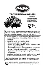
VENTED NATURAL GAS LOGS

MODELS

CRHEAV18RP 

CRHWV24RP 

CRHWV30RP

PFS

®

US

Summary of Contents for CRHEAV18RP

Page 1: ... the vicinity of this or any other appliance WHAT TO DO IF YOU SMELL GAS Do not try to light any appliance Do not touch any electrical switch do not use any phone in your building Immediately call your gas supplier from a neighbor s phone Follow the gas supplier s instructions If you cannot reach your gas supplier call the fire department Installation and service must be performed by a quali fied ...

Page 2: ...e 6 of this manual WARNING Improper installation adjustment al teration service or maintenance can cause injury or property damage Refer to this manual for correct in stallation and operational procedures For assistance or additional information consult a qualified installer service agency or the gas supplier This appliance may be installed in an aftermarket per manently located manufactured mobil...

Page 3: ... 5 W C Maximum 10 5 W C Propane LP Gas Minimum 11 W C Maximum 13 W C Add 4 in when using on off valve safety pilot kit For use if unit is converted to Propane LP gas SAFETY IMPORTANT Read this owner s manualcarefullyandcompletely before trying to assemble op erate or service this heater Improper use of this heater can cause serious injury or death from burns fire explosion electrical shock and car...

Page 4: ...ar to smoke turn off ap pliance and call a qualified service person Note During initial operation slight smok ing could occur due to log curing and the burning of manufacturing residues You may wish to add more ventilation by opening a window 7 Do not allow fans to blow directly into the fireplace Avoid any drafts that alter burner flame patterns Ceiling fans can create drafts that alter burner fl...

Page 5: ...e installation must be made by a licensed plumber or gas fitter in the Commonwealth of Mas sachusetts Sellers of unvented propane or natural gas fired supplemental room heaters shall provide to each purchaser a copy of 527 CMR 30 upon sale of the unit In the State of Massachusetts the gas cock must be a T handle type The State of Massachusetts requires that a flexible appliance connector cannot ex...

Page 6: ...irtychimneyfluemay createanddistributesootwithin the house Inspect chimney flue for damage NOTICE Installation service and repair of this appliance must be performed by a qualified installer service agency company or gas supplier experienced with this type of gas appliance Only factory authorized com ponents listed in these instructions may be used in accordance with the manufacturer s instruction...

Page 7: ...s Connection page 8 Gas line is on the left side If your gas line will be coming into the fireplace from the left side continue with step 2 2 Using a screwdriver remove cover plate on left side of burner pan see Figure 3 3 Unscrew burner inlet fitting from burner manifold see Figure 3 4 Place burner manifold in pan with thread ed opening facing opening on left side 5 Using thread sealant resistant...

Page 8: ...eter or greater to allow proper gas volume to log set If pipe is too small loss of pres sure will occur Installation must include an equipment shut off valve union and plugged 1 8 NPT tap Locate NPT tap within reach for test gauge hook up NPT tap must be upstream from log set see Figure 5 IMPORTANT Install equipment shutoff valve in an accessible location The equipment shutoff valve is for turning...

Page 9: ...ed 3 Pressurize supply piping system by either using compressed air or opening gas sup ply tank valve 4 Check all joints of gas supply piping sys tem Apply a noncorrosive leak detection fluid to gas joints Bubbles forming show a leak 5 Correct all leaks immediately 6 Reconnect log set and equipment shutoff valve to gas supply Check reconnected fittings for leaks Test Pressures Equal To or Less Tha...

Page 10: ...r If any ports appear blocked clear them by removing the burner manifold and reaming the ports with a modified paper clip or other suit able tool 5 When finished testing turn the gas shutoff valve OFF to extinguish all flames INSTALLING LOGS WARNING Failure to posi tion the parts in accordance with these diagrams or failure to use only parts specifically approved with this heater may result in pro...

Page 11: ...And place log 7 1 7 2 7 3 in front MODELS CRHWV24RP AND CRHWV30RP 5 Place log 5 on log 4 and log 2 6 Place log 6 1 6 2 6 3 in front 3 Place log 4 on log 2 and grate 4 Place log 3 on log 1 and log 4 1 Place vermiculite into burner pan Pull glowing ember loosely and sprinkle uniformly on the surface of vermiculite Insert log 1 into slots in rear log bracket on grate base 2 Insert log 2 into slots in...

Page 12: ...he control system and any gas control which has been under water LIGHTING INSTRUCTIONS 1 STOP Read the safety information above 2 Turn the gas shutoff valve to OFF 3 Wait five 5 minutes to clear out any gas If you still smell gas STOP Follow the safety information above If you don t smell gas go on to the next step 4 Light a match and lay it on top of the pan material about 2 from the end of the s...

Page 13: ...imney sweep should examine and clean the venting system of the fireplace ACCESSORIES Purchase these fireplace accessories from your local dealer If they can not supply these accessories contact customer service department for information EQUIPMENT SHUTOFF VALVE For all models Equipment shutoff valve with 1 8 NPT tap Fits 1 2 NPT pipe NVDWA1 ON OFF SAFETY PILOT VALVE KIT For all models Required for...

Page 14: ...rective Action Log set is smoking soot ing excessively Note It is natural and unavoidable for vented gas log sets to produce moderate levels of car bon soot where flames contact the logs 1 Poor fuel quality 2 Fireplace venting system not drafting properly 3 Excessive flame impinge ment or blockage 4 Improper fuel air mixture 5 Excessive gas supply pres sure 1 Contact local natural gas company 2 Ad...

Page 15: ...valve Gas odor during com bustion 1 Gas leak See Warning statement at top of page 14 1 Locate and correct all leaks see Checking Gas Connec tions page 9 TROUBLESHOOTING REPLACEMENT PARTS Contact authorized dealers of this product If they can t supply original replacement parts call Customer Service toll free at 1 866 573 6074 for referral information When calling Customer Service or your dealer ha...

Page 16: ...www usaprocom com 200035 01A 16 PARTS MODELS CRHEAV18RP CRHWV24RP AND CRHWV30RP 4 4 1 2 3 ...

Page 17: ... 6 1 BAVIN 1 Log 7 1 1 BAVIN 2 Log 7 2 1 BAVIN 3 Log 7 3 1 WAN300B Hardware Package 1 WAL08 02 1 2 Female x 5 8 Flare Adapter 1 WAB03 Damper Clamp 1 ITEM CRHWV24RP CRHWV30RP DESCRIPTION QTY 1 BL050 01 BL050 01 3 8 Female x 5 8 Flare Adapter 1 2 WAL06 01 WAL06 01 Injector Mounting 1 3 WAL07 02N WAL07 03N Injector 1 4 WAB18 01 WAB18 01 Grate Step 2 PARTS AVAILABLE NOT SHOWN WAL11 01 WAL11 01 Vermicu...

Page 18: ...__________ ________________________________________________________________________ ________________________________________________________________________ ________________________________________________________________________ ________________________________________________________________________ ________________________________________________________________________ ________________________...

Page 19: ...__________ ________________________________________________________________________ ________________________________________________________________________ ________________________________________________________________________ ________________________________________________________________________ ________________________________________________________________________ ________________________...

Page 20: ...nd instructions furnished with the unit WHAT IS NOT COVERED This warranty does not apply to parts that are not in original condition because of normal wear and tear or parts that fail or become damaged as a result of misuse accidents lack of proper maintenance or defects caused by improper installation Travel diagnostic cost labor transportation and any and all such other costs related to repairin...

Page 21: ...ropiedad lesiones personales o la pérdida de la vida No guarde niutilicegasolinauotrosvaporesylíquidos inflamables cerca de este aparato ni de cualquier otro QUÉ HACER SI PERCIBE OLOR A GAS No intente encender ningún aparato No toque ningún interruptor eléctrico no use nin gún teléfono en el edificio Llame inmediatamente a su proveedor de gas des de el teléfono de algún vecino Siga las instruccio ...

Page 22: ...ción ajuste alteración servicio o mantenimiento inadecuados pueden provo car lesiones o daños a la propiedad Consulte este ma nual para conocer los procedimientos de instalación y operación correctos Para obtener asistencia o informa ción adicionales consulte a un instalador capacitado agencia de servicio o al proveedor de gas Este aparato puede ser instalado en una casa móvil con ubicación perman...

Page 23: ...imos De La Cámara De Combustión Modelo Ancho frontal Ancho trasero Profundidad Altura CRHEAV18RP 60 9 cm 24 45 7 cm 18 38 1 cm 15 45 7 cm 18 CRHWV24RP 71 1 cm 28 55 9 cm 22 38 1 cm 15 45 7 cm 18 CRHWV30RP 86 4 cm 34 81 3 cm 32 40 6 cm 16 48 3 cm 19 FUEL INLET PRESSURE SPECIFICATIONS W C Natural Gas Mínimo 5 5 de c a Mínimo 10 5 de c a Propano LP Gas Máximo 11 de c a Máximo 13 de c a Sume 10 2 cm 4...

Page 24: ... llame al departamento de bomberos SEGURIDAD 3 Nunca instale el juego de leños en un vehículo recreativo en lugares donde haya cortinas mue bles telas u otros objetos inflamables a menos de 1 1 m 42 del frente de la parte superior o de los lados del juego de leños en áreas muy transitadas en áreas con mucho viento o con co rrientes de aire 4 Antes de instalar una chimenea que quema combustibles só...

Page 25: ...juego de leños y déjelo enfriar antes de realizar mantenimiento instalar lo o repararlo Sólo un técnico calificado debe instalar realizar el mantenimiento o reparar el juego de leños CARACTERÍSTICAS DEL PRODUCTO ENCENDIDO APAGADO EQUIPO DE VÁLVULA DE SEGURIDAD DEL PILOTO CON CONVERSIÓN DE PROPANO LP Para este artefacto hay disponible una válvula de encendido apagado o equipo de segu ridad piloto c...

Page 26: ...nergía Los materiales nuevos el mayor aislamiento y los nuevos métodos de construcción ayudan a reducir la pérdida de calor en las casas Los propietarios colocan burletes y masilla de calafateo alrededor de puertas y ventanas para impedir que ingrese aire frío y conservar el aire cálido adentro Durante los meses en los que se utiliza la calefacción los propietarios desean que sus hogares sean lo m...

Page 27: ...n una válvula de cierre del suministro de gas se debe instalar una ESPECIFICACIONES DE VENTILACIÓN PARA LA INSTALACIÓN El tiro y los conductos de ventilación de la chimenea deben tener un flujo de aire ade cuado Para comprobar si los conductos de ventilación tienen el flujo de aire correcto encienda uno de los extremos de un periódi co firmemente enrollado y colóquelo dentro del borde frontal de l...

Page 28: ...ndela Tubo colector del quemador Abrazadera del quemador Placa de cubierta Conector de entrada del quemador Tornillo Figura 4 Conexión del gas al artefacto Ensamblaje de la bandeja del quemador orientado hacia el frente de la chimenea Conector del adaptador Tubo conector de gas conector de entrada del quemador en el orificio y dentro del tubo colector del quemador Apriete con una llave inglesa 6 C...

Page 29: ...de leños consulte la Figura 5 IMPORTANTE Instale la válvula de cierre del equipo en un lugar accesible La válvula de cierre del equipo sirve para abrir o cerrar el paso de gas al artefacto Aplique un poco de sellador para uniones de tuberías a las roscas macho Esto evitará que el exceso de sellador ingrese a la tubería Una cantidad excesiva de sellador en la tubería podría tapar el inyector del qu...

Page 30: ...abriendo la válvula del tanque de su ministro de gas 4 Revise todas las juntas del sistema de tuberías de suministro de gas Aplique en todas las uniones algún líquido de detección de fugas que no sea corrosivo Si hay una fuga se formarán burbujas 5 Repare todas las fugas de inmediato 6 Vuelva a conectar el juego de leños y la válvula de cierre del equipo al suministro de gas Revise los conectores ...

Page 31: ...cios estén despejados y produzcan llamas de forma pareja en todo el quemador Si algún orificio parece estar obstruido despejado retirando el tubo colector del quemador y agrandando el orificio con un sujetapapeles adaptado u otra herramien ta adecuada 5 Cuando concluya las pruebas coloque la válvula de cierre en la posición de APAGADO para apagar todas las llamas INSTALACIÓN DE LEÑOS ADVERTENCIA N...

Page 32: ...2 Leño 6 1 Leño 2 Leño 4 MODELOS CRHWV24RP Y CRHWV30RP 1 Posición vermiculita en el molde del quemador Tire brasa suelta y espolvoree uniformemente sobre la superficie de la vermiculita Inserte leño 1 en las ranuras del soporte de registro posterior en la rejilla base 2 Inserte el leño 2 en las ranuras del soporte de leños a la derecha de la base de la rejilla Vermiculita y brasas al rojo vivo 3 C...

Page 33: ...osión D No use este aparato si alguna de sus partes estuvo sumergida en agua Llame inmediatamente a un técnico ca pacitado de servicio para que inspec cione el aparato y remplace las piezas del sistema de control y los controles de gas que hayan estado sumergidos en agua INSTRUCCIONES DE ENCENDIDO 1 ALTO Lea la información de seguridad que se encuentra arriba 2 Coloque la válvula de cierre de gas ...

Page 34: ...a de la llama en un total de tres horas CUIDADO Y MANTENIMIENTO Mantenga el área alrededor del juego de leños limpia y sin desechos De vez en cuando puede usar un cepillo de cerdas suaves para limpiar los leños Una vez por año una agencia calificada o un deshollinador certificado deben examinar y limpiar el sistema de ventilación de la chimenea ACCESORIOS Adquiera estos accesorios para chimeneas e...

Page 35: ... el aire que se utiliza para la combustión y producir olores Nota Todos los puntos para solución de problemas se listan en orden de funcionamiento Problema Causa posible Acción correctiva El juego de leños libera humo u hollín en exceso Nota es normal e inevi table que los juegos de leños a gas con ventila ción produzcan niveles moderados de carbón hollín donde las llamas entran en contacto con lo...

Page 36: ...alificado Eljuegodeleñosproduce olores indeseados 1 El juego de leños quema va pores de pintura aerosoles para cabello pegamentos limpiadores productos quí micos alfombras nuevas etc Consulte la advertencia IMPORTANTE de la página 35 2 Fuga de gas Consulte la Ad vertencia en la parte superior de la página 35 1 Abra el tiro al máximo Deje de usar productos que pro duzcan olor mientras el juego de l...

Page 37: ...rvicio al Cliente tenga preparados su nombre su dirección los números de modelo y de serie de su calentador la falla del calentador El tipo de gas utilizado propano PL o gas natural GN la fecha de compra Por lo general le pediremos que devuelva la pieza a la fábrica PIEZAS SIN GARANTÍA Comuníquese con los distribuidores autori zados de este producto Si no pueden sumi nistrarle piezas de repuesto o...

Page 38: ...www usaprocom com 200035 01A 38 PIEZAS MODELOS CRHEAV18RP CRHWV24RP Y CRHWV30RP 4 4 1 2 3 ...

Page 39: ...las piezas remplazables utilizadas en el calentador Al hacer un pedido de piezas siga las instrucciones listadas en Piezas de repuesto en la página 37 de este manual Art CRHWV24RP CRHWV30RP Descripción Cant 1 BL050 01 BL050 01 Adaptador acampanado de 5 8 x hembra de 3 8 1 2 WAL06 01 WAL06 01 Soporte del inyector 1 3 WAL07 02N WAL07 03N Inyector 1 4 WAB18 01 WAB18 01 Estribo de la rejilla 2 PIEZAS ...

Page 40: ...dor y dejarlo en buen estado de funcionamiento Las piezas de garantía deben obtenerse a través de ProCom Heating Inc que ofrece piezas originales de fábrica No utilizar repuestos originales de fábrica anula esta garantía El calentador debe ser instalado por personal calificado de con formidad con todos los códigos locales e instrucciones de la unidad LO QUE NO ESTÁ CUBIERTO Esta garantía no se apl...

Reviews: