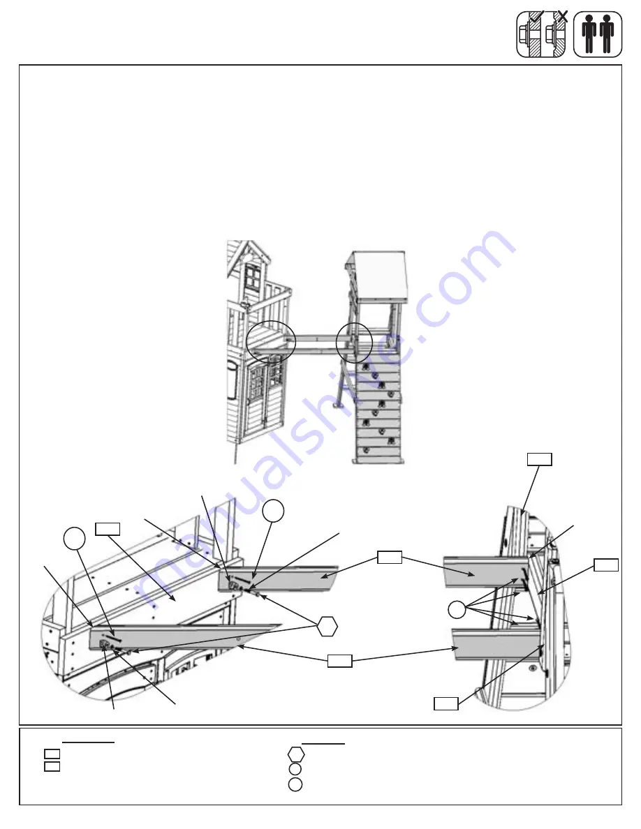
Step 49: Connect A Frame to Fort
Part 1
A:
Attach (490) Front Tunnel Support and (491) Back Tunnel Support to (092) Floor End with 1 (G8) 5/16 x
2” Hex Bolt (with lock washer and flat washer, t-nut previously installed) per board. Notice the bolt holes are
towards the bottom of the boards. (fig. 49.1 and 49.2)
B:
With a helper move the A Frame so the (490) Front Tunnel Support and (491) Back Tunnel Support sit flush
to the top and tight to (391) A Frame Floor Support. Each board should also sit tight against the inside of each
(390) A Frame Upright. Attach each board to each upright with 2 (S4) #8 x 3” Wood Screws per board. (fig
49.2 and 49.3)
C:
Attach (490) Front Tunnel Support and (491) Back Tunnel Support to (092) Floor End with 1 (S15) #8 x
1-3/4” Wood Screw per board. (fig. 49.2)
Fig. 49.2
490
Fig. 49.1
Fig. 49.3
S4
A Frame
Main Fort
Notice bolt hole location
Flush and
tight
Flush
390
A Frame
390
Hardware
2 x
5/16 x 2” Hex Bolt (5/16” lock washer & 5/16” flat washer)
4 x #8 x 3” Wood Screw
2 x
#8 x 1-3/4” Wood Screw
S4
Wood Parts
1 x
Front Tunnel Support FSC 2 x 4 x 56-23/64”
1 x
Back Tunnel Support FSC 2 x 4 x 36-43/64”
490
491
391
092
S15
S15
G8
G8
491
Main Fort
Notice bolt hole location
Flush
S15
5/16” Flat
Washer
5/16” Lock
Washer
124
support@cedarsummitplay.com


