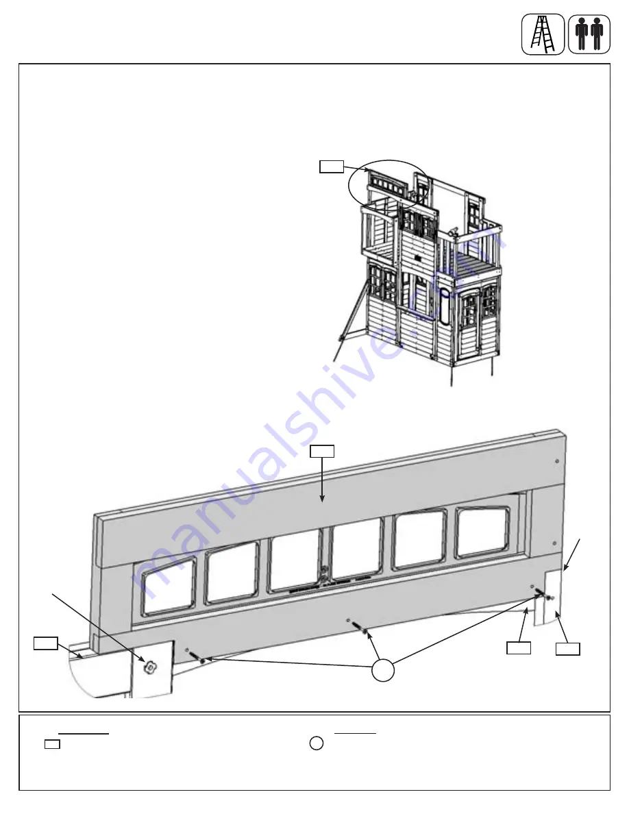
Fig. 22.1
Step 22: Attach Transom Front and Back
Part 1
A:
If the space is too tight loosen the bolt at the front of the assembly, as shown in fig. 22.2 then place (220)
Transom Front on top of (082) SL Post and (040) Cafe Wall Window Panel, behind (127) Front Top so the outside
edge is flush to the outside edge of (082) SL Post as shown in fig. 22.1 and 22.2.
B:
From inside the assembly attach (220) Transom Front to (127) Front Top with 3 (S15) #8 x 1-3/4” Wood
Screws. (fig. 22.2)
C:
Retighten the bolt loosened in Step A if loosened.
040
Front
Fig. 22.2
Hardware
1 x
Transom Front FSC 1-1/4 x 11-1/2 x 35-7/8”
220
Wood Parts
S15
220
Flush
082
127
Inside View
Front Wall
3 x
#8 x 1-3/4” Wood Screw
220
Loosen
this bolt
S15
86
support@cedarsummitplay.com


