Step 38: Attach SL Support to SL Bottom
Hardware
1 x
#8 x 1-3/4” Wood Screw
3 x
1/4 x 1-1/4” Pan Bolt
2 - (1/4” lock washer & 1/4” t-nut)
1 - (1/4” lock nut - previously removed)
1 x
5/16 x 2” Hex Bolt
(5/16” flat washer, 5/16” lock washer, 5/16” t-nut)
PB2
Other Parts
1 x TNR2 Post Mount
S15
G8
Wood Parts
1 x
SL Support FSC 2 x 4 x 26-1/4”
470
A:
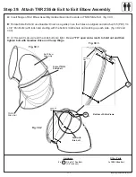
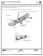
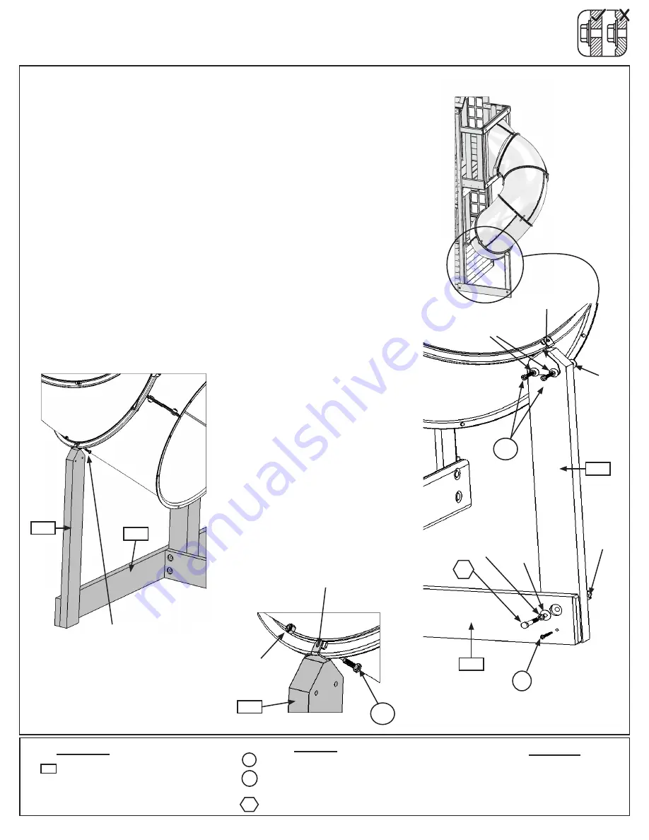
Loosely attach (470) SL Support to (050) SL Bottom using
1 (G8) 5/16 x 2” Hex Bolt (with flat washer, lock washer and
t-nut) in the top hole and 1 (S15) #8 x 1-3/4” Wood Screw in
the bottom hole. (fig. 38.1 and 38.2)
B:
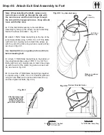
Insert (470) SL Support into TNR2 Post Mount and attach
with 2 (PB2) 1/4 x 1-1/4” Pan Bolts (with lock washer and
t-nut).
Keep these bolts loose.
(fig. 38.2)
C:
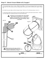
Use (470) SL Support as a guide to judge the proper bolt
location, remove the bottom pan bolt and nut.
The bolt will
no longer be needed, but keep the lock nut.
(fig. 38.3)
D:
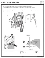
Attach the top of the TNR2 Post Mount to TNR2 Slide
Clamp Ring using 1 (PB2) 1/4 x 1-1/4” Pan Bolt (with the
previously removed lock nut). (fig. 38.4)
E:
Tighten all the bolts and the screw from this step.
DO NOT USE
USE IMAGE PG 129
DO NOT USE
USE IMAGE PG 129
S15
G8
PB2
Lock
Nut
Flat
Washer
T-Nut
T-Nut
Lock
Washer
Lock
Washer
x 2
PB2
TNR2 Post
Mount
TNR2 Post
Mount
Remove PB1 (1/4 x 3/4”
Pan Bolt first then install
PB2 (1/4 x 1-1/4” Pan
Bolt with previousely
removed lock washer)
Fig. 38.1
Fig. 38.2
Fig. 38.3
Fig. 38.4
050
470
470
050
470
116
support@cedarsummitplay.com


