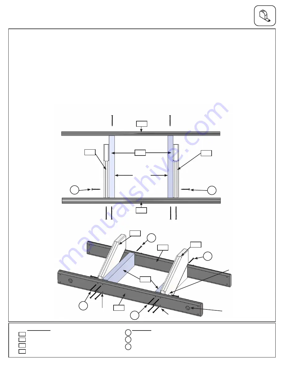
Step 31: Crowsnest Assembly
Part 1
A:
On flat level ground, lay out (320) Crowsnest Back and (321) Crowsnest Front so they face each other and
the countersunk holes on the (321) Crowsnest Front face out. Using the middle pilot holes as guides attach 2
(322) Crowsnest Joists with 2 (S3) #8 x 2-1/2” Wood Screws on the back and 2 (S4) #8 x 3” Wood Screws on the
front, per joist. The distance between (322) Crowsnest Joists should be 12-1/4”. (fig. 31.1 and 31.2)
B:
Tight to the outside of each (322) Crowsnest Joist attach 1 (323) Crowsnest Gusset with 1 (S7) #12 X 2” Pan
Screw per gusset. (fig. 31.1 and 31.2)
C:
Attach each (323) Crowsnest Gusset to (321) Crowsnest Front with 2 (S4) #8 x 3” Wood Screws per gusset.
(fig. 31.1 and 31.2)
Hardware
Fig. 31.2
Fig. 31.1
4 x
#8 x 2-1/2” Wood Screw
2 x
#12 x 2” Pan Screw
8 x
#8 x 3” Wood Screw
1 x
Crowsnest Back 5/4 x 4 x 36-1/2”
1 x
Crowsnest Front 2 x 4 x 36-1/2”
2 x
Crowsnest Gusset 2 x 6 x 15”
2 x
Crowsnest Joist 2 x 4 x 14-5/16”
320
321
Wood Parts
S3
323
Top View
322
323
S7
S7
321
320
323
323
320
322
321
Notice hole is on
this end
S3
S3
x 4
S4
S4
x 4
Notice countersunk
is on this face
Bottom View
323
S7
S4
x 2
x 2
322
12-1/4”
Flush
Flush
96
support@cedarsummitplay.com


