background image


CEDES


© 

CEDES

 Version 3.1 / 10

th

 April 2014 


Part No. 106 854


IMS 100 


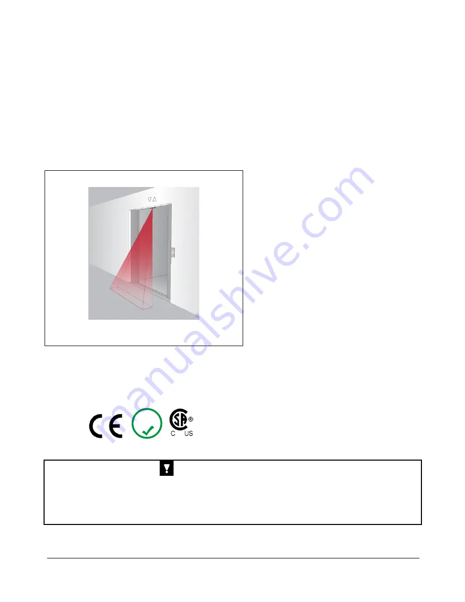
Door closing protection with IMS 100 


English 

Deutsch 

Français 


IMPORTANT NOTE 


FOLLOW THE INSTRUCTIONS GIVEN IN THIS MANUAL CAREFULLY. 

FAILURE TO DO SO MAY CAUSE CUSTOMER COMPLAINTS AND SERIOUS 

CALL BACKS. KEEP INSTRUCTION MANUAL ON SITE.


RoHS

Installation and Operation Manual


Bedienungsanleitung


Manuel d'installation et d'utilisation 


Maximizing door safety and comfort!


Summary of Contents for IMS 100

Page 1: ...ch Français IMPORTANT NOTE FOLLOW THE INSTRUCTIONS GIVEN IN THIS MANUAL CAREFULLY FAILURE TO DO SO MAY CAUSE CUSTOMER COMPLAINTS AND SERIOUS CALL BACKS KEEP INSTRUCTION MANUAL ON SITE RoHS Installation and Operation Manual Bedienungsanleitung Manuel d installation et d utilisation Maximizing door safety and comfort ...

Page 2: ...OOR PROTECTION SYSTEMS CANNOT PROVIDE ABSOLUTE SAFETY FOR ELEVATOR PASSENGERS PASSING THROUGH THE DOORWAY THEY CANNOT BE USED AS FAIL SAFE DEVICES OF THE DOOR MECHANISM THIS SAFETY FUNCTION MUST BE PROVIDED BY A FAIL SAFE FORCE AND KINETIC ENERGY LIMITER DO NOT USE THIS PRODUCT FOR THE PROTECTION OF DANGEROUS MACHINERY OR IN EXPLOSIVE ATMOSPHERES OR RADIOACTIVE ENVIRONMENTS USE ONLY SPECIFIC AND A...

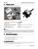
Page 3: ...t ing two dimensional 2D elevator door protection systems such as light curtains single beam sensors or mechanical edges to provide three dimensional 3D protection The IMS 100 can be used for new elevator installations or for modernization of existing elevator systems As an extension to existing door protection devices the purpose of the IMS 100 sensor is to monitor the entrance area of the elevat...

Page 4: ...n be accomplished in sever al ways depending on the elevator control system requirements The following sections provide examples for incor porating the IMS 100 into an existing system The contents of each delivery depend on the system ordered Should you have any queries regarding the contents of this delivery or if you require application assistance please contact CEDES or your local distributor 3...

Page 5: ... os si it ti io on ns s Center opening car door The sensor is placed in the door frame in the center of the door opening Orientation Cable going out on slam post side or toward center of cab entrance opening Side opening car door The sensor is placed in the door frame as near to the slam post as possible Orientation The sensor must be mounted with the cable outlet facing the door jamb Center surfa...

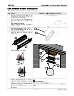
Page 6: ...m 2 for the sensor ca ble For side opening doors Keep a distance of 22 mm from the cor ner of the doorway 2 Mount the sensor box 1 with the two 3 5 mm self tapping screws 3 on the elevator cab transom 2 3 Snap the sensor 4 into the mounting bracket 5 Align the sensor to the lobby 4 Route cable up through the 10 mm hole 3 8 inch in the elevator cab transom Slide the sensor 4 with the mounting brack...

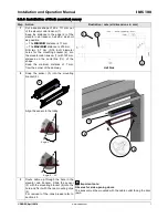
Page 7: ... 4 7 mm 3 16 inch diameter holes for the mounting bracket 4 into the elevator cab transom 1 with 120 mm distance on the centerline CL of the shape Keep the minimum distance of 7 mm from the corner of the doorway 2 Snap the sensor 3 into the mounting bracket 5 Align the sensor to the lobby Important note Observe for side opening doors The sensor must be mounted with the cable outlet facing the door...

Page 8: ...MS 100 can also be configured so that the semi conductor output will automatically transition to active high e g 24 VDC after a fixed 18 second timer has expired e g for nudging The timeout setting can be changed based on the signal connected to the timeout selector white con ductor as shown in the following table Timeout selector connection white conductor has to be connected either or Timeout se...

Page 9: ... wired in accordance with your elevator control system requirements turn the power on and verify that the system operates as expected When the CEDES power line converter is connected to 85 265 VAC the green LED will be illuminated to indicate that 24 VDC power is present for powering the IMS 100 sensor and that the input voltage to the power supply is greater than 85 VAC The IMS 100 has several IR...

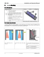
Page 10: ...do om m d do oo or r o op pe en ni in ng gs s In case the elevator door is made of glass or a shiny material e g mirror the door may not be detected by the sensor during closure For these applications place a piece of reflective tape on the inner side of the elevator cab door that passes in front of the sensor as the door closes see figure 4 and 5 Y x Inner door of the cabin Door frame Reflective ...

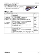
Page 11: ...nfluence the light curtain Dirty sensors Excessive EMC interference e g from door drive or fluorescent lamps Section 3 3 2 Section 3 Please refer to light curtain manual Door closing although person or object in the IMS 100 detection area Are the light curtain and IMS 100 connected correctly Is the relay connected correctly COM NO NC Is the alignment done properly Position of IMS 100 inside elevat...

Page 12: ...tput PNP Max output load 50 mA 100 nF Output logic LOW object HIGH no object Response time 350 ms Indication LED red LED on LED off Object detected No object detected Max optical illumination LED power 0 5 W Max recalibration time 1 5 s Connection cable and electrical connection Length sensor cable 0 5 m Length connection cable 2 8 m Diameter Ø 3 5 mm Material PVC black Connection M8 4 pin Wires A...

Page 13: ...S DIE AUFZUGSTEUERUNG ERKENNEN UND DEN BETREFFENDEN AUFZUG AUSSER BETRIEB NEHMEN GRUNDSÄTZLICH KÖNNEN TÜRSICHERUNGSSYSTEME KEINE ABSOLUTE SICHERHEIT FÜR AUFZUGBENUTZER BIETEN SIE KÖNNEN NICHT ALS AUSFALLSICHERE KOMPONENTEN DES TÜRMECHANISMUS EINGESETZT WERDEN DIESE SICHERHEITSFUNKTION MUSS DURCH AUSFALLSICHERE SCHLIESSKRAFTBEGRENZER GEGEBEN SEIN IMS 100 DARF NICHT FÜR DIE ABSICHERUNG VON GEFÄHRLIC...

Page 14: ...n be stehende zweidimensionale 2D Aufzugtürsiche rungssysteme wie Lichtvorhänge Einzellichtschran ken oder mechanische Flanken integriert um einen drei dimensionalen 3D Schutz zu bieten IMS 100 lässt sich sowohl für neu eingebaute Aufzuganlagen als auch für die Modernisierung bereits bestehender Anlagen verwenden Als Erweiterung bestehender Türsicherungsvor richtungen dient der Sensor IMS 100 dazu...

Page 15: ...neue oder bereits bestehende Aufzugskabine integrieren In den folgenden Ab schnitten finden Sie Beispiele für den Einbau des IMS 100 in ein bereits bestehendes System Der Lieferumfang kann je nach Art des bestellten Systems variieren Wenn Sie Fragen zum Lieferumfang haben oder Hilfe bei der Anwendung benötigen wenden Sie sich bitte an CEDES oder an Ihren Händler vor Ort 3 3 M Mo on nt ta ag ge e B...

Page 16: ...nde Kabinentüren Der Sensor wird im Tür rahmen in der Mitte der Tür öffnung platziert Ausrichtung Kabelaustritt auf beiden Seiten möglich Seitlich öffnende Kabinentüren Der Sensor wird seitlich so nah wie möglich am An schlag in den Türrahmen montiert Ausrichtung Kabelaustritt in Richtung Türpfosten montieren Aufputzmontage in der Mitte Hinterwandmontage in der Mitte Aufputzmontage seitlich Hinter...

Page 17: ...n 22 mm von der Ecke der Türöffnung 2 Befestigen Sie das Aufputzgehäuse 1 mit den beiden 3 5 mm Blechschrauben 3 an der Türzarge 2 3 Lassen Sie den Sensor 4 in den Mon tagebügel 5 Richten Sie den Sensor auf den Vor raum aus 4 Führen Sie das Kabel durch das 10 mm Loch in der Türzarge Schieben Sie den Sensor 4 mit dem Montagebügel 5 in das Loch und befestigen Sie ihn mit zwei Montage Clips 6 Zur Ent...

Page 18: ...on 4 7 mm für den Montagebügel 4 in die Türz arge 1 Achten Sie auf den Mindestabstand von 7 mm zur Ecke der Türöffnung 2 Lassen Sie den Sensor 3 in den Mon tagebügel 4 Richten Sie den Sensor auf den Vor raum aus Wichtiger Hinweis Bei seitlich öffnenden Türen ist zu beachten dass der Kabelaustritt des Sensors IMS 100 in Richtung Türpfos ten orientiert ist und in genau dieser Position montiert werde...

Page 19: ...rieren dass der Halbleiter Ausgang nach Ablauf eines festgelegten 18 Sekunden Intervalls automatisch auf aktiv high z B 24 VDC umschaltet IMS 100 kann mit zwei Zeitmodi betrieben werden Diese werden mit der Beschaltung des Time out Ein gangs weisse Ader gewählt Der Time out Eingang muss entweder oder ange schlossen werden siehe Tabelle Anschluss Time out Selector weisse Ader Time out Einstellung A...

Page 20: ...d das dazugehörige Türsiche rungssystem gemäss Ihren Aufzugsteuerungsanfor derungen montiert und verkabelt sind schalten Sie den Strom ein und überprüfen Sie ob der Sensor korrekt funktioniert Wenn das CEDES Schaltnetzteil an 85 265 VAC angeschlossen ist leuchtet die grüne LED und zeigt an dass 24 VDC für den Betrieb des IMS 100 Sensors anliegen und die Eingangs spannung zum Netzteil höher ist als...

Page 21: ... je ek kt t Ist die Aufzugstür aus Glas oder einem spiegelndem Material ist es möglich dass der 3D Sensor IMS 100 die Tür während der Schliessung nicht erkennt Ist dies der Fall kleben Sie die beiliegende Reflektorfolie auf die Innenseite der Aufzugskabine Die Position der Folie ist oben genau im Sichtfeld vom Sensor zu Positioniern siehe Abbildung 4 und 5 Y x Kabineninnentür Türzarge Reflektorfol...

Page 22: ...t Verschmutzte Sensoren Übermässige EMV Störungen z B von Türantrieb oder Leuchtstoffröhren Kapitel 3 3 2 Kapitel 3 Montageanleitung des Lichtvor hangs Tür schliesst sich obwohl sich Personen oder Ob jekte sich im Erfassungs bereich IMS 100 befinden Sind der Lichtvorhang und der IMS 100 ordnungsgemäss angeschlossen Ist das Relais richtig angeschlossen COM NO NC Ist die Ausrichtung ordnungsgemäss I...

Page 23: ...NP Max Ausgangslast 50 mA 100 nF Ausgangslogik LOW Objekt HIGH kein Objekt Ansprechzeit 350 ms LED Anzeige rot LED an LED aus Objekt erkannt Kein Objekt erkannt Max Leistung LED Beleuchtung 0 5 W Max Nachkalibrierungszeit 1 5 s Anschlusskabel und elektrische Anschlüsse Länge Sensorkabel 0 5 m Länge Anschlusskabel 2 8 m Durchmesser Ø 3 5 mm Material PVC schwarz Anschluss M8 4 polig Drähte AWG26 bra...

Page 24: ... ÊTRE DÉTECTÉES PAR LE SYSTÈME DE COMMANDE D ASCENSEUR QUI À SON TOUR DEVRAIT METTRE L ASCENSEUR HORS SERVICE EN GÉNÉRAL LES SYSTÈMES DE PROTECTION POUR PORTES NE PEUVENT PAS FOURNIR UNE SÉCURITÉ ABSOLUE POUR LES PASSAGERS DE L ASCENSEUR ILS NE PEUVENT PAS ÊTRE UTILISÉS COMME DISPOSITIFS DE SÉCURITÉ DU MÉCANISME DE LA PORTE CETTE FONCTION DE SÉCURITÉ DOIT ÊTRE FOURNIE PAR UN BORD MÉCANIQUE DE SÉCU...

Page 25: ...e ou bords mécaniques pour fournir une protection en trois dimensions 3D L IMS 100 peut être utilisé pour les nouvelles installations d ascenseurs ou pour la mo dernisation des systèmes d ascenseurs existants Dans le prolongement des dispositifs de protection existants pour les portes l objectif du capteur IMS 100 est de surveiller la zone d entrée de la porte de l ascenseur et de détecter les per...

Page 26: ...ns en fonction du type de contrôleur de porte Les sections suivantes fournissent des exemples pour incorporer le capteur IMS 100 dans un système existant Le contenu de chaque livraison dépend du système commandé Si vous avez des questions concernant le contenu de la livraison ou si vous souhaitez une assistance pour l application merci de contacter CEDES ou votre distributeur local 3 3 I In ns st ...

Page 27: ...Porte à ouverture centrale Le capteur est placé dans le linteau de la porte au centre de l ouverture de celle ci Orientation Le câble va en direction du montant de la porte ou vers le centre de l entrée de la cabine Porte à ouverture latérale Le capteur est placé dans le linteau aussi près que pos sible du montant de la porte Orientation Le capteur doit être monté avec le câble en direction du mon...

Page 28: ...ur Pour portes à ouverture latérale Garder une distance de 22 mm du coin du passage du montant de la porte 2 Monter la boite du capteur 1 avec les deux vis auto taraudeuses de 3 5 mm 3 sur le linteau de la cabine d ascen seur 2 3 Placer le capteur 4 dans le support de montage 5 Aligner le capteur vers le palier 4 Passer le câble à travers le trou de 10 mm dans le linteau de la cabine d ascenseur I...

Page 29: ...montage 4 dans le linteau de la cabine d ascen seur 1 avec 120 mm de distance par rapport à la ligne centrale CL de la découpe Garder une distance minimum de 7 mm du coin de passage de la porte 2 Insérer le capteur 3 dans la fixation de montage 4 Diriger le capteur vers le palier Note importante Attention particulière pour portes à ouverture latérales Le capteur doit être monté avec la sortie câbl...

Page 30: ...utomatiquement vers active signal haut ex 24 VDC après un temps écoulé de 18 secondes e g pour nudging Le type de temporisation s effectue en raccordant le fil blanc comme montré dans le tableau suivant La sélection de la tempo risation fil blanc se fait de la manière suivante Réglage temporisation Connecté à USP 18 s Connecté à 0 VDC GND Infini Note importante Le temps est pris en compte après la...

Page 31: ...ntrôle de votre ascen seur mettre sous tension Quand le convertisseur de tension CEDES est connecté à 85 265 VAC la LED verte s allume pour indiquer la présence du 24 VDC au capteur IMS 100 et que la tension d alimen tation est plus grande que 85 VAC L IMS 100 à plusieurs IR LEDs qui sont utilisés pour illuminer la zone observée en infrarouge Si vous re garder directement le capteur quand il est s...

Page 32: ...as des portes d ascenseur en verre ou avec une surface brillante ex miroir la porte pourrait ne pas être détectée par le capteur pendant la fermeture Pour ces applications placer un morceau de scotch réfléchissant sur le côté intérieur de la porte de la cabine d ascenseur à l endroit passant devant le capteur lors de la fermeture de la porte voir figure 4 et 5 Figure 4 Scotch réfléchissant pour po...

Page 33: ...ux Capteurs encrassés Interférences excessive des EMC par ex de la commande de porte ou des lampes fluorescentes Section 3 3 2 Section 3 Se référer au manuel du rideau lumineux La porte ferme bien qu il y ai présence de per sonne ou d objet dans l aire de surveillance de l MS 100 Le rideau lumineux et l IMS 100 sont ils correctement connectés Le relais est il correctement connecté COM NO NC L alig...

Page 34: ...A Sortie PNP Max charge en sortie 50 mA 100 nF Logique de sortie BAS objet HAUT Pas d objet Temps de réponse 350 ms Indication des LED rouge LED allumé LED éteint Objet détecté Pas d objet détecté Max illumination optique LED 0 5 W Max temps de recalibration 1 5 s Câble de raccorde ment et connexion électrique Longueur câble du capteur 0 5 m Longueur câble de connexion 2 8 m Diamètre Ø 3 5 mm Maté...

Page 35: ... CEDES April 2014 www cedes com 35 6 6 C Ce er rt ti if fi ic ca at te e o of f c co om mp pl li ia an nc ce e K Ko on nf fo or rm mi it tä ät ts se er rk kl lä är ru un ng g C Ce er rt ti if fi ic ca at t d de e c co on nf fo or rm mi it té é ...

Page 36: ...S 100 Installation and Operation Manual 36 www cedes com CEDES April 2014 7 7 C CS SA A c ce er rt ti if fi ic ca at te e C CS SA A Z Ze er rt ti if fi ik ka at t C Ce er rt ti if fi ic ca at t C CS SA A ...

Page 37: ...Installation and Operation Manual IMS 100 CEDES April 2014 www cedes com 37 ...

Page 38: ...IMS 100 Installation and Operation Manual 38 www cedes com CEDES December 2009 ...

Page 39: ...Installation and Operation Manual IMS 100 CEDES April 2014 www cedes com 39 ...

Page 40: ...tion Manual CEDES AG Switzerland Tel 41 81 307 2323 Fax 41 81 307 2325 info cedes com www cedes com CEDES AG is certified according to ISO 9001 2008 CEDES AG reserves the right to modify or change technical data without prior notice ...

Reviews: