background image

MiniMax


Bedienungsanleitung


14


www.cedes.com 

© CEDES/Juni 2009


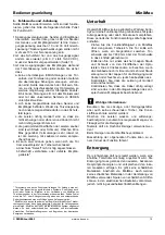
3. Kabel richtig führen um Beschädigungen 

zu vermeiden 

Damit die Kabel gut geführt sind, ist geeignetes Mon-
tagematerial zu verwenden, z.B. Kabelschutztüllen, 
Kabelbinder, Kabelschutzschläuche (abhängig vom 
verwendeten Montageset). 

 Wenn die Kabel nicht sauber geführt und gut 

fixiert wurden, kann dies die Lebensdauer deutlich 
reduzieren. Eine Zerstörung kann durch Schwingen 
der Kabel und durch Einhängen im Liftschacht erfol-
gen! Die Montageanweisung für die Kabel ist sorgfäl-
tig zu befolgen. Diese Anleitung ist in der entspre-
chenden Montageanleitung, des entsprechenden 
Montagesets zu finden. 


4. 

Anschluss der Sender- und Empfänger-

Kabel 

Stellen Sie sicher, dass die Versorgungsspannung 
für den MiniMax zwischen 10 und 30 VDC liegt. Für 
einen einwandfreien Betrieb muss die Span-
nungsversorgung min. 100 mA liefern können. 
MiniMax erfüllt die Standards bezüglich elektro-
magnetischer Störungen (EMV), jedoch ist ein 
Schutz gegenüber Störungen in jedem Fall zu em-
pfehlen. 
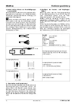
Führen Sie die Anschlusskabel von MiniMax nicht zu 
nahe an Kabel mit hoher Spannung oder Strom ent-
lang. Ebenfalls sollten die Kabel nicht zu nahe am 
Motor des Türantriebs respektive am Leistungsteil 
der Türsteuerung (VVVF-Antriebe) vorbeiführen. 


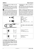
Sender 

braun: 

+10 – 30 VDC 

blau: GND 

(0V) 

Empfänger 

braun: 

+10 – 30 VDC 

blau: GND 

(0V) 

schwarz: Ausgang 
weiss: 

Ausgang Selector* (s. unten) 

Empfänger

Sender

Sicherung 0.5 A slow blow

GND

+10 – 30 VDC


Die Spannungsversorgung muss mit einer 
trägen Sicherung von max. 500 mA abgesi-
chert werden. 

*Ausgangsspannung: 


GND                              +10 – 30 V 

Ausgang Selector (weisses Kabel) 
verbunden mit  
+10 – 30 VDC (braunes Kabel) 

*Ausgangsspannung: 


+10 – 30 V                             GND 

Ausgang Selector (weisses Kabel) 
verbunden mit 
GND (blaues Kabel) 


5. Einschalten und Funktionstest 

Nach der korrekten Installation des MiniMax kann die 
Spannungsversorgung eingeschaltet werden. Die 
grünen LED in den Steckern (weiss: Sender, blau: 
Empfänger) müssen nun leuchten und zeigen damit 
an, dass Spannung vorhanden ist. Die orange LED  
leuchtet, wenn sich ein Objekt im Schutzfeld befin-
det; ist das Schutzfeld frei leuchtet die orange LED 
nicht. 


Summary of Contents for MiniMax-159

Page 1: ...Espa ol C US EN 81 70 IMPORTANT NOTE FOLLOW THE INSTRUCTIONS GIVEN IN THIS MANUAL CAREFULLY FAILURE TO DO SO MAY CAUSE CUSTOMER COMPLAINTS AND SERIOUS CALL BACKS KEEP INSTRUCTION MANUAL ON SITE Insta...

Page 2: ...DES AND REGULATIONS THAT PERTAIN TO INFRARED AND PHOTOELECTRIC DOOR PROTECTION DEVICES IN CANADA PARTICULAR ATTENTION SHOULD BE GIVEN TO CLAUSES 2 13 5 1 AND 2 13 5 2 CAN CSA B44 B89 MINIMAX MUST BE I...

Page 3: ...ed and no longer active This func tion allows operation of the device even with partial damage or blockage due to vandalism Up to two non adjacent sensor elements in the emitter and receiver edge can...

Page 4: ...d towards the receiver edge Although MiniMax is very tolerant of bright sunlight it is better to mount the receiver edge so that no sun light shines directly into the curved front area of the receiver...

Page 5: ...ellow wire to the grounded door panel to avoid elec tromagnetic noise pickup Hence the door panels shall be grounded Fix the connector with a cable tie wrap to the door panel or mounting profile Figur...

Page 6: ...dent to guard against interference Therefore do not guide MiniMax connection cables close to cables carrying high voltage and or high current The MiniMax cables should also be mounted as far away as p...

Page 7: ...e conditions doors can close even with an obstacle present Therefore there must be by code other safety means to prevent passengers from being hurt by the elevator doors These dangerous situations sho...

Page 8: ...pull PNP and NPN Output logic NO and NC selectable Response time 25 120 ms Operating range 0 3 m 0 10 feet Protection height 1 800 mm 6 feet First beam above lower end of edge 20 mm 0 78 Weight 0 3 k...

Page 9: ...9 159 1 Location for side mounting 2 Location for front mounting 3 Edge length can be adjusted individually between min and max edge length Max edge length 2114 mm 0 3000 Protection height 1800 mm Emi...

Page 10: ...UND INTERNATIONALEN GESETZEN UND VORSCHRIFTEN BEREINSTIMMT DIE INFRAROT UND PHOTOELEKTRISCHE T RSCHUTZVORRICHTUNGEN BETREFFEN IN KANADA MUSS FOLGENDEN VORSCHRIFTEN BESONDERE AUFMERKSAMKEIT GESCHENKT...

Page 11: ...tigt MiniMax ist dann wieder in Betrieb Diese Funktion erlaubt die Nutzung von MiniMax obwohl ein Element z B durch Vandalismus be sch digt wurde Bis zu zwei nicht benachbarte Ele mente in der Sender...

Page 12: ...rer Lichtvorh nge Sender von Lichtschranken oder andere st rende Lichtquellen in den Empf nger strahlen Obschon MiniMax sehr unempfindlich ge gen ber Fremdlicht ist ist es besser die Empf nger leiste...

Page 13: ...erdeten T rfl gel Somit vermei den Sie elektromagnetische St rungen Bitte achten Sie darauf dass der T rfl gel geerdet ist Fixieren Sie den Stecker mit einem Ka belbinder entweder am T rfl gel oder pf...

Page 14: ...edoch ist ein Schutz gegen ber St rungen in jedem Fall zu em pfehlen F hren Sie die Anschlusskabel von MiniMax nicht zu nahe an Kabel mit hoher Spannung oder Strom ent lang Ebenfalls sollten die Kabel...

Page 15: ...ende Sicherheitsmassnahmen wie Stillegung des Aufzugs einleiten 2 MiniMax wie auch alle anderen auf dem Markt erh ltlichen T rabsi cherungssysteme kann keine absolute Sicherheit f r Aufzugspassa giere...

Page 16: ...P und NPN Logik am Ausgang NO und NC selektierbar Ansprechzeit 25 120 ms Einsatzdistanz 0 3 m Schutzfeldh he 1800 mm Erster Strahl gemessen vom unteren Leistenende 20 mm Gewicht 0 3 kg Sonnenlicht 75...

Page 17: ...osition f r seitliche Montage 2 Position f r seitliche Frontmontage 3 Profill nge kann individuell zwischen max und min Profill nge angepasst werden Max Profill nge 2114 mm 0 3000 Schutzfeldh he 1800...

Page 18: ...NATIONALES AFF RENTES QUI CONCERNENT LES DISPOSITIFS INFRAROUGE OU PHOTO LECTRIQUES DE PROTECTION POUR PORTES AU CANADA UNE ATTENTION PARTICULI RE DOIT ETRE ACCORD E AUX PRESCRIPTIONS SUIVANTES 2 13 5...

Page 19: ...est alors nouveau en fonctionnement Cette fonction permet d utiliser Mi niMax bien qu un l ment ait t endommag par ex par vandalisme Jusqu deux l ments non voisins dans la barre mettrice ou r ceptrice...

Page 20: ...d autres ri deaux lumineux ou aucune autre source lumineuse g nante ne doivent rayonner dans le r cepteur Bien que MiniMax soit tr s peu sensible la lumi re ext rieure il vaut mieux monter la barre r...

Page 21: ...porte pour viter les parasites lectromagn tiques Bien entendu ces m mes panneaux se ront mis la terre Fixer le connecteur avec un collier de serrage au panneau de la porte ou du profil de montage Fig...

Page 22: ...r les per turbations lectromagn tiques CEM Une pro tection contre les perturbations est recommand e dans tous les cas Ne guidez pas les c bles de rac cordement de MiniMax trop pr s le long de c bles h...

Page 23: ...son entre le MiniMax et la commande de la porte ou de la commande de la porte De tels d fauts doi vent tre d tect s par la commande de porte ou d ascenseur qui doit mettre en uvre des mesures de s cur...

Page 24: ...bilit de s lection NO et NC Temps de r action 25 120 ms Distance d utilisation 0 3 m Hauteur du champ de protection 1800 mm Premier rayon mesur de l extr mit inf rieure de la barre 20 mm Poids 0 3 kg...

Page 25: ...ion en face 2 Emplacement de montage pour la fixation avant 3 La longueur totale du bord optique peut tre ajust e individuellement Longueur maxi du bord optique 2114 mm 0 3000 Hauteur du champ de prot...

Page 26: ...ANTO SIA CONFORME A TUTTE LE NORME E I REGOLAMENTI IN VIGORE PER I DISPOSITIVI DI PROTEZIONE PORTE A RAGGI INFRAROSSI E FOTOELETTRICI IN CANADA DOVR ESSERE INOLTRE PRESTATA PARTICOLARE ATTENZIONE ALLE...

Page 27: ...consente di utilizzare MiniMax anche nel caso in cui un elemento sia stato guastato ad esempio a causa di atti vandalici Il si stema in grado di disattivare sino a due elementi non adiacenti nel tras...

Page 28: ...on utilizzare trasmettitori di altre barriere elettroniche trasmettitori di cortine luminose n altre fonti luminose che possano distur bare il ricevitore MiniMax non particolarmente sensibile alla luc...

Page 29: ...Cavo giallo verde Collegare il filo giallo verde con il battente della porta con la messa a terra per evitare disturbi elettro magnetici Collegare la presa con un cavo di raccordo al battente della po...

Page 30: ...prevedere dispositivi di protezione nei confronti di tali interferenze Il cavo di collegamento di MiniMax non deve essere posizionato nei pressi di cavi ad alta tensione o di cavi destinati al passagg...

Page 31: ...dere che la porta chiuda anche in presenza di un ostacolo A causa di ci deve esserci per normativa un ulteriore sistema di sicurezza che prevenga danni alle persone Queste situazioni perico lose devon...

Page 32: ...emissione NO e NC selezionabile Tempo di risposta 25 120 msec Range operativo 0 3 m Altezza protezione 1800 mm Primo raggio a partire dall estremit inferiore della barriera 20 mm Peso 0 3 kg Luce sola...

Page 33: ...laterale 2 Posizione per il montaggio anterione 3 L altezza della barriera pu essere regolata in un intervallo di valori compresi tra un min e un max Max altezza della barriera 2114 mm 0 3000 Altezza...

Page 34: ...N CUMPLA CON TODOS LOS C DIGOS Y NORMAS REGULADORAS RELEVANTES TANTO NACIONALES COMO INTERNACIONALES EN RELACI N CON DISPOSITIVOS INFRARROJOS Y FOTOEL CTRICOS DE PROTECCI N DE PUERTAS EN CANAD SE DEB...

Page 35: ...niMax vuelve entonces a activarse y seguir funcionando Esta funci n permite que el dispositivo siga funcionando incluso si un elemento sufre da os causados por ejemplo por actos de vandalismo De este...

Page 36: ...ojos o de una barrera fotoel ctrica ni ninguna otra fuente luminosa perturbadora debe emitir su luz hacia el list n receptor Aunque MiniMax tolera muy bien las luces extra as es mejor montar el list n...

Page 37: ...con el tierra del ala de la puerta As se evitan perturbaciones electro magn ticas Por favor compruebe que el ala de la puerta est puesta a tierra Fije el conector con una abrazadera bien en el ala de...

Page 38: ...contra interferencias en cada caso Por lo tanto no distribuya los cables de conexi n de MiniMax demasiado cerca de cables de alta tensi n y o corriente de alta intensidad Para evitar problemas de inte...

Page 39: ...naturaleza sistemas a prueba de fallas Por esta raz n no es posible detectar cada falla en el MiniMax o en la comunicaci n del MiniMax con el control de la puerta o en el propio control de la puerta...

Page 40: ...cnicos Tensi n de alimentaci n 10 30 VCC Consumo de corriente normalmente 60 mA protegido con un fusible de acci n retardada de 0 5 A Salida Semiconductor Potencia de ruptura m x 120 mA Polaridad de s...

Page 41: ...lateral 2 Posici n para fijaci n frontal 3 La longitud de perfil puede ajustarse individualmente entre el m x y m n de la longitud del mismo M x longitud de perfil 2114 mm 0 3000 altura del campo prot...

Page 42: ...MiniMax 42 www cedes com CEDES June 2009 MINIMAX 2 13 5 1 2 13 5 2 CAN CSA B44 B89 MINIMAX Ex...

Page 43: ...MiniMax CEDES June 2009 www cedes com 43 MiniMax CEDES 1800 6 MiniMax 10 30V PNP NPN MiniMax MiniMax MiniMax 45 MiniMax MiniMax CEDES 1990 MiniMax 50 MiniMax MiniMax 20 PCB 20 45 cegard Max...

Page 44: ...MiniMax 44 www cedes com CEDES June 2009 1 2 MINIMAX 79 MiniMax 5 6 1 1 Minimax...

Page 45: ...MiniMax CEDES June 2009 www cedes com 45 75 000 lux E R E R E R R E A 1 6 A 1 6 A MiniMax 79 A B 2100 7 1 A 2 B...

Page 46: ...MiniMax 46 www cedes com CEDES June 2009 3 4 2 4 MiniMax 10 30 100 MiniMax EMI MiniMax MiniMax VVVF drives EMI 10 30 VDC 0V 10 30 VDC 0V 0 5A GND 10 30 VDC 500 5 MiniMax...

Page 47: ...MiniMax CEDES June 2009 www cedes com 47 6 MiniMax 1 10 30V 10 2 3 4 a CEDES b c d MiniMax 5 1 a b 2 1 2 MiniMax 6 1800...

Page 48: ...NRTL C CSA EMV 89 336 EC changed 92 31 EC CSA Certificate no No 187273 1485166 LR109459 EN 81 70 EN 50081 1 2 EMI Emission EN 50082 1 2 EMI Immunity EN12015 EMI Emission for elevators and escalators...

Page 49: ...MiniMax CEDES June 2009 www cedes com 49 0 MiniMax 847 847 427 427 7 7 1282 1282 1717 1717 79 159 1 2 3 2114 mm 0 3000 1800 mm 1860 mm 2104 1 2110 3 2 3 16 12 4 6 4 8 7 7 1 4 1 0 1 1 0 4...

Page 50: ...MiniMax Installation and Operation Manual 50 www cedes com CEDES June 2009 Declaration of conformity...

Page 51: ...Installation and Operation Manual MiniMax CEDES June 2009 www cedes com 51 CSA Certificate...

Page 52: ...AG Switzerland Tel 41 81 307 2323 Fax 41 81 307 2325 info cedes com www cedes com CEDES AG is certified according to ISO 9001 2008 CEDES AG reserves the right to modify or change technical data withou...

Reviews: