background image

31

• 

CEDIMA

® • Technical Documentation • All rights reserved according to ISO 16016 • Changes serving technical progress reserved •

Preparation and operation

CF•13.3 B / CF•13.3 B-L

ENGLISH

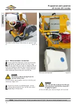
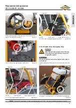
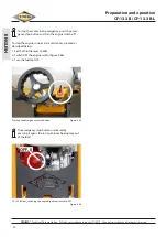
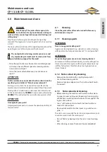
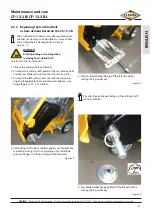
Water container mounted 

Figure 4.56

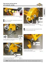
Securing the water container with rubber strap to the right of the 

joint cutter frame  

Figure 4.57

Securing the water container with rubber strap to the left of the joint 

cutter frame  

Figure 4.58

Connecting hose with Gardena coupling for connection to the 

water container control/shut-off valve 

Figure 4.59

Summary of Contents for CF 13.3 B

Page 1: ...d drilling Table saws Wall saws Wire saws Hydraulic units Special machinery Operating manual maintenance manual and safety notes CF 13 3 B CF 13 3 B L Change index 000 Issue date 2021 11 05 Translatio...

Page 2: ...ical photocopying recording or otherwise or translated into a foreign language without the prior written consent other than permitted under copyright law The information contained in this publication...

Page 3: ...ity evaluation RL 2000 14 EC Annex V Hereby we confirm that in the sense of EC Directive 2006 42 EC Annex II 1 A dated 2006 05 17 modifications inclusive of the European Parliament and the Council the...

Page 4: ...product information description Chapter 2 Technical specifications and accessories Chapter 3 Basic safety instructions Chapter 4 Preparation and operation Chapter 5 Cutting with the CEDIMA joint cutt...

Page 5: ...protect the environment and the user against splash wastewater the saw blade guard is equipped with a splash guard mat 12 The cutting shaft with the diamond saw blade is driven by a modern Honda petro...

Page 6: ...mentation All rights reserved according to ISO 16016 Changes serving technical progress reserved General product information ENGLISH Figure 1 2 7 1 2 3 6 10 12 13 8 14 4 9 15 16 17 18 19 5 Joint cutte...

Page 7: ...ption at full load approx 3 7 l h approx 4 7 l h Engine oil 1 1 l SAE 10W 30 Engine start reversing starter with pull wire Ambient temperature for operation from 15 C to 60 C Height of operation up to...

Page 8: ...the location of operation use Measurement uncertainty acc to DIN EN 12096 DANGER Risk of injury when exceeding the daily maximum of vibration load 2 2 Vibration acceleration values hand arm vibration...

Page 9: ...tion The operating manual uses the following terms and sym bols for important information Notice special information regarding the economic use Mes sages marked with the symbol Note contain important...

Page 10: ...ing the table saw Clean the component Check the component DANGER Warning of hot fluids DANGER Warning of pinching or crushing Important statements are printed in italics Statements concerning safety a...

Page 11: ...anual must be supplemented by instructions covering the duties involved in supervising and notifying special organizational features such as job organization work flows or the personnel entrusted with...

Page 12: ...ear the ground of all things that could impede the work Ensure a safe stand on even firm stable ground and make sure to keep the balance any time Never use the machine in a way that might be contrary...

Page 13: ...secure it against inad vertent movement rolling off and accidental restart unauthorized use 3 5 3 Special work related to the maintenance and repair of the machine and troubleshooting disposal Observe...

Page 14: ...trician and in accordance with the applica ble electrical engineering rules If provided for in the relevant regulations the power supply to machine parts on which inspection mainte nance or repair wor...

Page 15: ...illed fluids or lubricants must be removed immedi ately using binding agents Use binding agents Fluids or lubricants must not penetrate into the soil or public sewage system Used fluids or lubricants...

Page 16: ...um level However to avoid the inconvenience of a sudden shutdown you should check the engine oil level before each start Aligning frame with engine horizontally Figure 4 1 1 2 DANGER Risk of burns Som...

Page 17: ...water container from the joint cutter sec tion 4 9 2 and figures 4 6a and 4 6b CF 13 3 B L water containerremoved position of the fuel filler cap Figure 4 6b 2 Fill up the tank with the appropriate f...

Page 18: ...belt tension For the optimum check of the V ribbed belt tension use the measurement device recommended by the V ribbed belt manufacturer tension to 70 Hz If necessary dismount the saw blade guard and...

Page 19: ...ake Figure 4 12 17 4 6 Mounting the diamond saw blades 4 6 1 General information DANGER Risk of injury due to incorrect and or incor rectly mounted saw blade ATTENTION Exclusively use diamond saw blad...

Page 20: ...ng dimensions ATTENTION 300 500 mm 25 4 mm 8 0 mm max 13 0 mm Diamond saw blade for CF 13 3 B CF 13 3 B L Figure 4 13 When mounting more than 2 saw blades mount match ing spacer disks between the saw...

Page 21: ...nd thread on the right side of the cutting shaft Remove the inner clamping screw of the saw blade guard Figure 4 15 13 Lift up and remove the blade guard Figure 4 17 Remove the rear fixing screw Figur...

Page 22: ...shaft must match the direction of rotation of the saw blade Mount the right or left clamping ring according to the saw blade mounting width figure 4 22 section 4 6 4 Diamond saw blade with correct dir...

Page 23: ...diamond saw blades Diamond saw blades are designed to sharpen themselves during operation while cutting However if cutting often into strong steel reinforcements or hard material with low abrasion th...

Page 24: ...utting side as here described with seperated blade guard 13 Dismount cutting shaft guard left Figure 4 27 Cutting shaft guard dismounted Figure 4 28 Right hand thread on the left side of the cutting s...

Page 25: ...saw blade guard Figure 4 31 13 Remove screw with washer from saw blade guard Figure 4 32 13 Screw with washer removed from saw blade guard Figure 4 33 Loosening screw at the saw blade guard holder Fi...

Page 26: ...F 13 3 B L ENGLISH Left side of cutting shaft saw blade guard holder Figure 4 37 Left side of cutting shaft saw blade guard plugged to saw blade guard holder Figure 4 38 13 13 Screw with washer provid...

Page 27: ...4 43 Coupling cooling water connection to the saw blade guard see sec tion 4 9 Figure 4 42 24 Clamping diamond saw blade with right hand thread cutting shaft nut on the left side of the cutting shaft...

Page 28: ...ENGLISH 13 Cutting shaft guard right mounted Figure 4 47 4 7 Adjusting the cutting depth indication The cutting depth indication can be adjusted exactly to the diameter of the diamond saw blade Scratc...

Page 29: ...Therefor dislocate the pointer rod accordingly as required 4 9 Cooling and flushing water supply DANGER Risk of pinching or crushing when coupling the connecting hose and when actuating the water con...

Page 30: ...ning of the joint cutter and makes the cut more even and cleaner DANGER Risk of injury when tensioning the water container rubber strap Check the rubber strap hook for correct seat at in the joint cut...

Page 31: ...13 3 B L ENGLISH Water container mounted Figure 4 56 Securing the water container with rubber strap to the right of the joint cutter frame Figure 4 57 Securing the water container with rubber strap t...

Page 32: ...er engine in closed or poorly ventilated rooms ATTENTION Do not overturn the joint cutter when starting it Put one foot onto the right rear wheel so that you can pull the starter handle with the start...

Page 33: ...te freely Lift the saw blade off the surface to be cut and or out of the cut Unlocking the emergency stop button press the actuated button again so that the button jumps out Figure 4 61 Front switchin...

Page 34: ...he red mushroom head jumps out of the lock Pressing the emergency switch button Figure 4 65 CF 13 3 B front switching the engine ignition switch to OFF Figure 4 66 OFF 0 To stop the motor in an emerge...

Page 35: ...the diamond saw blade to full speed 12 Open the water shutoff valve pressurised water or water container and thus control the required water amount 13 Slowly lower the diamond saw blade to the desired...

Page 36: ...e engine of the joint cutter 5 Wait until the cutting shaft and the diamond saw blade has come to a standstill 6 If necessary stop the compressed water supply and disengage the external pressure water...

Page 37: ...his will extend the service life of your joint cutter ATTENTION Use original spare parts Only original spare parts can ensure the operational safety of the joint cutter 6 1 Cleaning Clean the joint cu...

Page 38: ...rosion Regular checks and any repairs should be carried out to preserve the corrosion protection After cleaning and in case of longer periods on non use provide the metallic sliding parts and the mova...

Page 39: ...elt grooved pulleys 5 3 4 5 4 Lubricating points 3 1 2 5 4 Threaded spindle 3 1 2 1 3 4 4 Motor 3 7 8 8 8 8 8 8 8 4 Parking brake 3 3 5 4 Reachable connecting elements screws 5 3 4 5 4 Wheels 3 1 1 3...

Page 40: ...the V ribbed belt as described and check the tension again 9 Tighten the clamping screw at the V ribbed belt tension er and the lock nut of the adjustment screw figures 6 1 and 6 2 10 Check the true r...

Page 41: ...tting shaft saw blade 2 Dismount the cutting shaft guard or the saw blade guard and the saw blade mounted on the left section 4 6 4 3 Dismount the left cutting shaft nut with the clamping ring and if...

Page 42: ...ing sleeve off the cutting shaft using the taper clamping bush figures 6 10 and 6 11 Do not use force 10 7 V ribbed belt guard cover mounted with screws Figure 6 7 8 V ribbed belt guard cover dismount...

Page 43: ...use sharp or pointed objects to pull on the V ribbed belt Do not damage the V ribbed belt The V ribbed belt must lie completely on the grooved pulleys Do not tilt the grooved pulley Do not use force 1...

Page 44: ...ed pulley figure 6 15 Ensure that the area between cutting shaft grooved pulley taper clamping bush and cutting shaft is clean degrease Align the cutting shaft grooved pulley the taper clamping bush a...

Page 45: ...2 Plug the saw blade holder flange onto the left side of the cutting shaft parallel key Figure 6 20 24 10 21 V ribbed belt guard cover mounted with screws Figure 6 19 17 20 Tension the V ribbed belt F...

Page 46: ...d belt and re tension if necessary 6 7 3 Engine maintenance Changing engine oil Change the engine oil according to the operating manual of the engine DANGER Risk of injury due to hot engine oil Wear a...

Page 47: ...ool down slowly after stopping the engine Let the heat baffle plate cool down 1 Dismount the water container and the rubber strap sec tion 4 9 2 figure 6 25 Water container and rubber strap dismounted...

Page 48: ...out with compressed air if necessary max 6 bar Uncouple the external compressed water hose The filled water container elevates the centre of grav ity and can cause the joint cutter to tilt during tran...

Page 49: ...viously mentioned issues about trans port section 7 1 Release the V ribbed belt Turn the cutting shaft engine approx monthly by hand for some revolutions Run the functions of the joint cutter approx m...

Page 50: ...Check cutting shaft for free movement Lift cutting shaft saw blade from the ground out of the cut Move operating lever to Start position Release emergency stop button check repair or replace engine if...

Page 51: ...w blade mounted against direction of rotation Saw blade not adjusted to the material to be cut possibly too hard Saw blade not matched to the machine performance Diamond segments are blunt Mount saw b...

Page 52: ...t cutting shaft saw blade hole Saw blade flange dirty and or defective Cutting shaft has shrunk Too much bearing play of the cutting shaft Turn the saw blade location bore and let a ring be fit in Cle...

Page 53: ...turer s operating manual Operation related wear is not a reason for claims to defects Wearing parts for the construction devices mentioned in the operating manual such as core drilling and sawing mach...

Page 54: ...ment of the purchase price which in any other case is excluded We are not liable for compensation on account of a defect or damage subsequent to a defect unless these occur on account of an intention...

Page 55: ......

Page 56: ...ORE DRILL MACHINES hand or drill rig machines with electric or hydraulic drilling motor drill diameter from 12 to 1250 mm WALL SAWS ANDWIRE SAWS electric hydraulic and electro hydraulic wall saws with...

Reviews: