44
•
CEDIMA
® • Technical Documentation • All rights reserved according to ISO 16016 • Changes serving technical progress reserved •
Maintenance and care
CF•13.3 B / CF•13.3 B-L
ENGLISH
Do not tilt the taper clamping bush!
Unscrew the stud accordingly!
Do not use force!
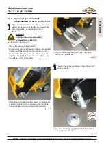
15. Set cutting shaft grooved pulley onto the centre disk of
the cutting shaft
Figure 6.14
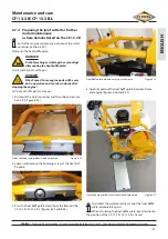
16. Place a stud into the taper clamping bush as guide
(opposite of the gap) and put the taper clamping bush
according to the parallel key onto the cutting shaft into
the cutting shaft grooved pulley (figure 6.15),
Ensure that the area between cutting shaft grooved
pulley, taper clamping bush and cutting shaft is clean,
degrease!
Align the cutting shaft grooved pulley, the taper clamping
bush and the cutting shaft to each other! Pay attention to
the cone of the taper clamping bush and grooved pulley!
Grease the two studs slightly and screw them in
evenly with the correct torque (20 Nm, decisive are
the manufacturer's specifications)!
Fill the 3 holes of the taper clamping bush with grease to
prevent corrosion!
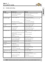
19. Plug the sleeve onto the left side of the cutting shaft
Figure 6.17
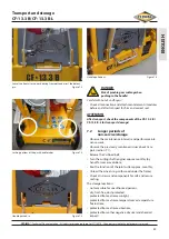
18. Screw in studs evenly
Figure 6.16
5
17. Taper clamping bush with guide stud inserted in the
grooved pulley on the cutting shaft
Figure 6.15
5
Summary of Contents for CF 13.3 B
Page 55: ......

