background image

ENGLISH

12

• 

CEDIMA

® • Technical Documentation • All rights reserved acc. to ISO 16016 • Changes serving technical progress reserved •

Basic safety instructions

for joint cutters

3.2.4.11 For machines driven by rotary electric power, 

adhere to the direction of rotation of the tool as 

specified by the manufacturer to avoid the loosening of 

the tool!

3.2.4.12 During start-up and shut-down procedures always 

watch the indicators in accordance with the operating 

manual.

3.2.4.13 Before you start up the machine or set it to motion, 

make sure that the starting or running machine does not 

create any hazard to other persons’ health.

3.2.4.14 The driver/ operator position is only to be filled by 

the user. Keep third parties away from the machine!

3.2.4.15 Start and operate the machine only from the 

control location (CF-22 E.800, behind the machine)!

3.2.4.16 It must be ensured that the operator has 

an unobstructed view of the work area at all times and 

that he can intervene at any time in the working process.

3.2.4.17 Before you start working with the machine, check 

that the braking, steering, signaling and lighting systems 

are fully functional!

3.2.4.18 Hydraulic and water hoses as well as electric lines 

must be laid in such a way that damage by crossing or by 

the tool cannot occur!

3.2.4.19 The cutting operation must be performed 

using the wet cutting method in order to prevent the 

formation of hazardous clouds of fine dust and to 

increase the service life of the cutting tool.

3.2.4.20 When using the wet-cutting method, always make 

sure that there is enough water at the proper places. 

Make sure there is enough cooling water at the cutting 

groove!

3.2.4.21 When using the dry-cutting method, make sure 

there is enough suction to remove the dust!

3.2.4.22 If substances can emerge during the work which 

are health-damaging or explosive, e.g. dust, slurry, the 

national health- and safety rules apply!

3.2.4.23 Moving the machine outside the workplace is only 

allowed without saw blade!

3.2.4.24 When operating the machine on public roads, 

ways and places always observe the traffic regulations 

in force and, if necessary, make sure beforehand that 

the machine complies with the relevant road vehicle 

regulations.

3.2.4.25 Always control the accident-proof accommodation 

of the accessories before the transport of the machine!

3.2.4.26 Never travel across slopes exceeding 5%.
3.2.4.27 Always use safety ropes when operating the 

machine on sloping terrain exceeding 15%!

3.2.4.28 Before leaving the machine always secure it 

against inadvertent movement and unauthorized use!

II 

 Special tasks when using the machine 

and during upkeep work as well as 

troubleshooting in daily operation; 

disposal

3.2.4.29 Observe the adjustment, maintenance and 

inspection activities and intervals set out in the 

operating manuals, including information on the 

replacement of parts or assemblies! These activities may 

be performed by skilled personnel only!

3.2.4.30 Brief the operating personnel before initiating 

special repair or maintenance activities! Appoint a 

person to supervise such activities! 

3.2.4.31 In any work concerning the operation, adaptation 

to production requirements, conversion or adjustment 

of the machine and its safety-oriented devices or any 

work related to inspection, maintenance and repair, 

always observe the start-up and shut-down procedures 

described in the operating manual as well as the 

instructions on maintenance activities!

3.2.4.32 If necessary, secure a large area around the 

location where maintenance of the machine is to be 

performed.

3.2.4.33 Service and repair work may only be carried 

out with a fully lowered blade shaft/frame or through 

securing the frame by means of approved trestles! 

Hydraulic valves for raising the frame must be opened 

(pressure relief)!

3.2.4.34 Maintenance and repair work may be carried out 

only if the machine is placed on level and solid ground 

and secured against inadvertent movement!

3.2.4.35 If the machine is completely shut down for 

maintenance or repair work, it must be secured against 

inadvertent restarting:

–  remove the key and/or disconnect the power supply

–  attach a warning sign at the main switch.

3.2.4.36 When using a lifting gear for replacing individual 

parts or large assemblies make sure that the parts/

assemblies are carefully attached to the lifting gear 

and secured in place to avoid hazardous conditions! 

Use only suitable and technically perfect lifting gear 

and suspension systems with adequate lifting capacity! 

Never work or stand under suspended loads!

3.2.4.37 The fastening of loads and the instructing of 

crane/industrial truck operators should be entrusted to 

experienced persons only! The instructor must be within 

sight or sound of the operator!

3.2.4.38 Before performing any maintenance/repair 

activities clean the machine, especially the connectors 

and screwed joints, and remove any oil, dirt and 

preservative agents! Never use aggressive detergents! 

Use lint-free cleaning rags!

Summary of Contents for CF-22 E.800

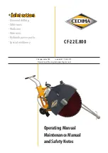
Page 1: ...te 17 05 2019 Translation of the original operating manual Operating Manual Maintenance Manual and Safety Notes CF 22 E 800 Joint cutters Diamond drilling Table saws Wall saws Wire saws Hydraulic powe...

Page 2: ...of the original operating manual All rights reserved acc to DIN ISO 16016 No part of this documentation may be reproduced adapted stored in a retrieval system or transmitted in any form or by any mean...

Page 3: ...mantled into 3 modular parts for transport Measured sound pressure level LWA 94 dB A Guaranteed sound pressure level LWA d 98 dB A Procedure of conformity evaluation RL 2000 14 EC Annex V Hereby we co...

Page 4: ...E 800 EC Declaration of conformity Chapter 1 Technical specifications and accessories Chapter 2 Description of the joint cutter CF 22 E 800 Chapter 3 General safety instructions for handling the joint...

Page 5: ...lta switch Protection class IP 54 Saw blade receptacle Support taps right and left 25 4 mm Driver pin 8 0 mm Max saw blade mounting width 10 0 mm RPM cutting shaft 2240 min 1 Max saw blade 800 mm Max...

Page 6: ...mes include times for fuelling water supply tool change machine set up and transport securing the location of operation use Measurement uncertainty acc to DIN EN 12096 DANGER Risk of injury when excee...

Page 7: ...ting operations The 3 transport friendly assemblies enable fast transport e g in a hatchback car and allow the CF 22 E 800 to be assembled directly at locations that are difficult to access The assemb...

Page 8: ...d in two self aligning pedestal bearings The precision engineered shaft has a 25 4 mm diameter blade mounting flange The front pointer is mounted on the joint cutter frame It enables the user to cut a...

Page 9: ...ms and symbols for important information Note Special information regarding the economic use Messages marked with the symbol Note contain important information and it is separated from other text ATTE...

Page 10: ...erials provisioning and or wearing of personal protective equipment or road traffic regulations 3 2 2 3 This operating manual must be supplemented by instructions covering the duties involved in super...

Page 11: ...nd the possibility to render first aid in case of accidents 3 2 4 2 Assemble the machine on an even hard and stable surface The stability is to be ensured Remove any obstacle which could impede the fu...

Page 12: ...Always use safety ropes when operating the machine on sloping terrain exceeding 15 3 2 4 28 Before leaving the machine always secure it against inadvertent movement and unauthorized use II Special tas...

Page 13: ...ly when you can be sure that the touched or cut power line has been switched off 3 2 5 7 When operating the machine always keep a safe distance from electric lines If work is to be carried out in the...

Page 14: ...ate the hydraulic system 3 2 9 4 Be careful when handling hot fluids or lubricants risk of serious injuries or burns Especially when handling fluids or lubricants with temperatures exceeding 60 C make...

Page 15: ...ore recommissioning 3 2 10 13 Even when the transport of the machine only involves a minor relocation disconnect it from all external power supply lines Before using the machine again make sure that t...

Page 16: ...e must be located in the upper section of the threaded spindle Attach the blade guard Dismantling Proceed in reverse order to Assembling Rocker with motor and cutting shaft Central bolt Figure 4 1 4 1...

Page 17: ...elect the saw blade type according to the material to be cut Observe the diameter of the saw blade receptacle and the blade shaft Please refer to chapter Technical specifications and accessories for d...

Page 18: ...ted on the saw blade is an arrow for the cutting direction If this arrow is not visible the cutting direction of the saw blade can be determined as follows During cutting a tail is formed behind the d...

Page 19: ...ply The CEDIMA joint cutter CF 22 E 800 is supplied with water via a GEKA coupling The water shut off valve located behind it allows you to stop or reduce the supply of water Geka water coupling with...

Page 20: ...tter OFF and disconnect it from the electrical supply line and only then switch the current generator OFF Otherwise voltage surges can damage the electric system of the joint cutter ATTENTION Observe...

Page 21: ...r delta reversing switch to 0 and allow the motor to come to a standstill Then turn the reversing switch in the opposite direction to the Y position for the first start Once the rated speed is reached...

Page 22: ...th adjustment spindle Hold the joint cutter firmly during this process Make deep cuts in several passes Cutting depth per cut Asphalt up to a depth of 10 cm Concrete up to a depth of 6 cm After loweri...

Page 23: ...has to be changed after complete wear of the diamond segments in case of changes in the material to be cut The diamond saw blade absolutely must be changed if it is worn down unevenly if diamond segme...

Page 24: ...fe of your joint cutter ATTENTION Use original spare parts Only original spare parts can ensure the operational safety of the joint cutter 5 1 Cleaning Clean the joint cutter after each use and before...

Page 25: ...ing promotes further wear due to adhering dust Check all connections and connecting elements between the components and retighten any loosened screw connections see section 5 4 5 3 Maintenance and car...

Page 26: ...5 3 4 3 4 Threaded spindle 1 3 2 3 4 4 Engine housing 3 1 Engine 3 7 1 3 4 5 4 Parking brake 3 3 5 4 Reachable connecting elements nut screws 5 Wheels 3 1 1 3 4 5 4 h operating hours Depending on load...

Page 27: ...rrect operation by actuating the testing facility User 5 6 Security check of the electric equipment acc to BGV A3 5 implementing regulations paragraph 1 No 2 Table 1B Recurrent tests of non stationary...

Page 28: ...the motor and the V belt pulley on the motor shaft The V belts will then slide off the edges of the V belt pulleys and wear out faster A sudden crack with negative consequences for the diamond saw bl...

Page 29: ...to run out Dismount the diamond saw blade Do not transport the joint cutter with the diamond saw blade mounted Transport the joint cutter upright and horizontally Swivel the front pointer cantilever...

Page 30: ...ive Loose electric contact in the electrical system Engine defective Cutting shaft blocked cutting shaft with saw blade not lifted from the ground or out of the cut Mains fuse s tripped Motor not yet...

Page 31: ...on the cutting shaft Driver pin defective missing Replace insert driver pin Diamond saw blade stops under load V belt slips V belt defective torn Driver pin defective missing Tensioning V belts Replac...

Page 32: ...conditions for construction equipment such as drilling and sawing machines as well as associated assemblies 1 The supplier must be notified in writing of any evident defects in the machine within 14...

Page 33: ...of the purchase price which in any other case is excluded We are not liable for compensation on account of a defect or damages subsequent to a defect unless these occur on account of an intention or...

Page 34: ...o 900 mm CORE DRILL MACHINES hand or drill rig machines with electric or hydraulic drilling motor drill diameter from 12 to 1250 mm WALL ANDWIRE SAWS electric hydraulic and electro hydraulic wall saws...

Reviews: