Issue 4.0
CEECO
Communication Equipment & Engineering Company
PROPRIETARY
12
5.0 REMOTE
MONITORING
5.01
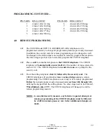
The CEECO Model WPP-531-D(EMER)-RP-ADA telephone can remotely
monitor the area in which it has been installed by using another telephone.
Simply follow the steps of the next sections:
5.02
Place a
call
to
the CEECO
telephone
from another phone. The CEECO
telephone will
answer itself
after the number of rings programmed in section
3.12. The CEECO telephone
sends out two tones
as a prompt for the next step.
5.03
Using the calling telephone,
dial # *
which will turn on the microphone
for
remote monitoring
of the area of the CEECO telephone.
5.04
Dial # to end
the monitoring mode and the CEECO phone will hang up.
6.0 INSTALLATION NOTES AND ASSEMBLY INSTRUCTIONS
NOTE: Installation should only be performed by qualified persons and in
accordance with all applicable codes and standards.
6.01 Recommended tools and test equipment:
DTMF Test Set
3/8" Nut driver
Volt/Ohm
Meter
5/16"
nut
driver
CEECO Security Tool, 301-064
Flat blade screw driver
6.02 Using a 301-064 security tool (sold separately) loosen and remove the four (4)
security screws. Separate the faceplate assembly from the weatherproof housing
by pulling the faceplate forward.
6.03 Run the telephone line/wire into the enclosure and terminate on the RJ11C
modular jack inside, as depicted on page 17 of this manual. The CEECO-
provided modular jack
must
be utilized, as it contains required over-voltage
protection. Mount the housing in the intended location using the four mounting
holes provided. There is a pole-mounting bracket available, which is sold
separately. Outdoor conduit and proper sealing techniques should be utilized in
order to prevent water entry.
6.04 The use of a gas tube station protector is recommended. The station ground
should not exceed 50 ohms.
6.05 Run an AC line cord into the weatherproof housing. Locate the strobe light
relay board on the telephone assembly, which is located underneath the main
660-000 printed circuit board. Please refer to the A/C installation guide on page
18 of this manual. The strobe light relay board has four terminal positions on it.
Two are concealed under the main circuit board with the strobe light already
connected. The two available terminals for the A/C line are accessible at the
edge of the main circuit board. Attach the AC line cord to the AC contacts as
indicated.


