Technical Manual
GAM40(& GAM40K, GAM40B)
v2.0EN
4. Electrical Connections
Installation of this project involves a hazard of electric shocks. We strongly rec-
ommend you contract a professional installer. Incorrect installation places you
in danger and may irreversibly damage the product and the equipment con-
nected to it. In compliance with the NF C 15-100 standard, pool lights installed
in Volume 0 must always be powered by VLSV (Very low safety voltage). Al-
ways cut off the power upstream before handling the electrical installation.
Risk of electric shock. Only connect to a circuit which is protected by a 30mA
circuit-breaker. If you are not sure if these types of devices are fitted, contact
a qualified electrician.
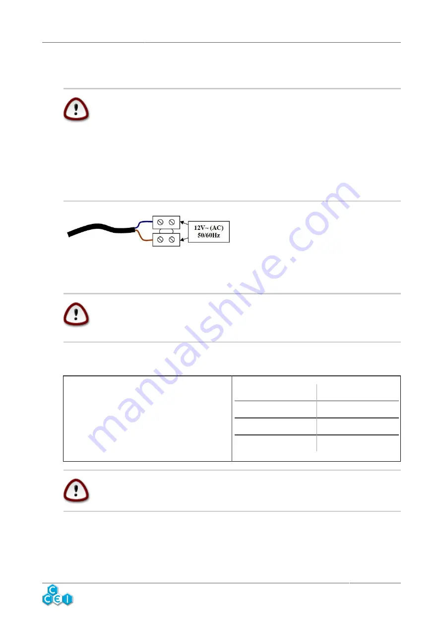
The electrical connection must be performed dry,
in a sealed connection box whose cable glands
must be tightened in order to avoid any water in-
filtration.
Once startup and the operation tests are complete, it is recommended to drown the connection with
a reusable soft hydrophobic insulating gel. (ref. CCEI PNSP0002)
The external flexible cables for these light fittings may not be replaced.
If a cable is damaged, the fitting must be destroyed or returned to the manu-
facturer for recycling.
5. Transformer Power
The transformer to be used must have a sec-
ondary voltage of 12V (12.5V depending on the
model). The power of the transformer must be in
line with the power of the lights to be connected.
In any case, the sum of the powers of the lights
must remain below or equal to the power of the
transformer.
Transformer Power
Max no. of GAM40
50VA
1
100VA
2
300VA
6
Preferably use transformers sold in power supply units from the same manu-
facturer.
6. Projector Protection
Independent protection is necessary for each GAM40. Protection must be ensured in the secondary
of the transformer using fuses or breakers at 4A or more.
www.c-
cei.fr
6


