HI-PE multi-zone --- Rev.
FI 050 GB 60K10 v2_1
12
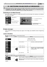
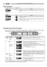
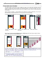
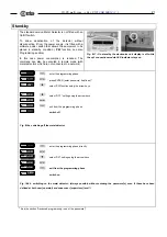
Electrical assembly
All connecting cables between the gateway and the power supply or other external devices must be properly
fixed and protected so as to achieve the best performance from the detector and avoid accidental injury to
people who might trip over them.
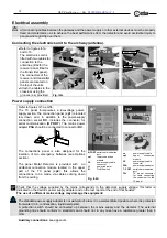
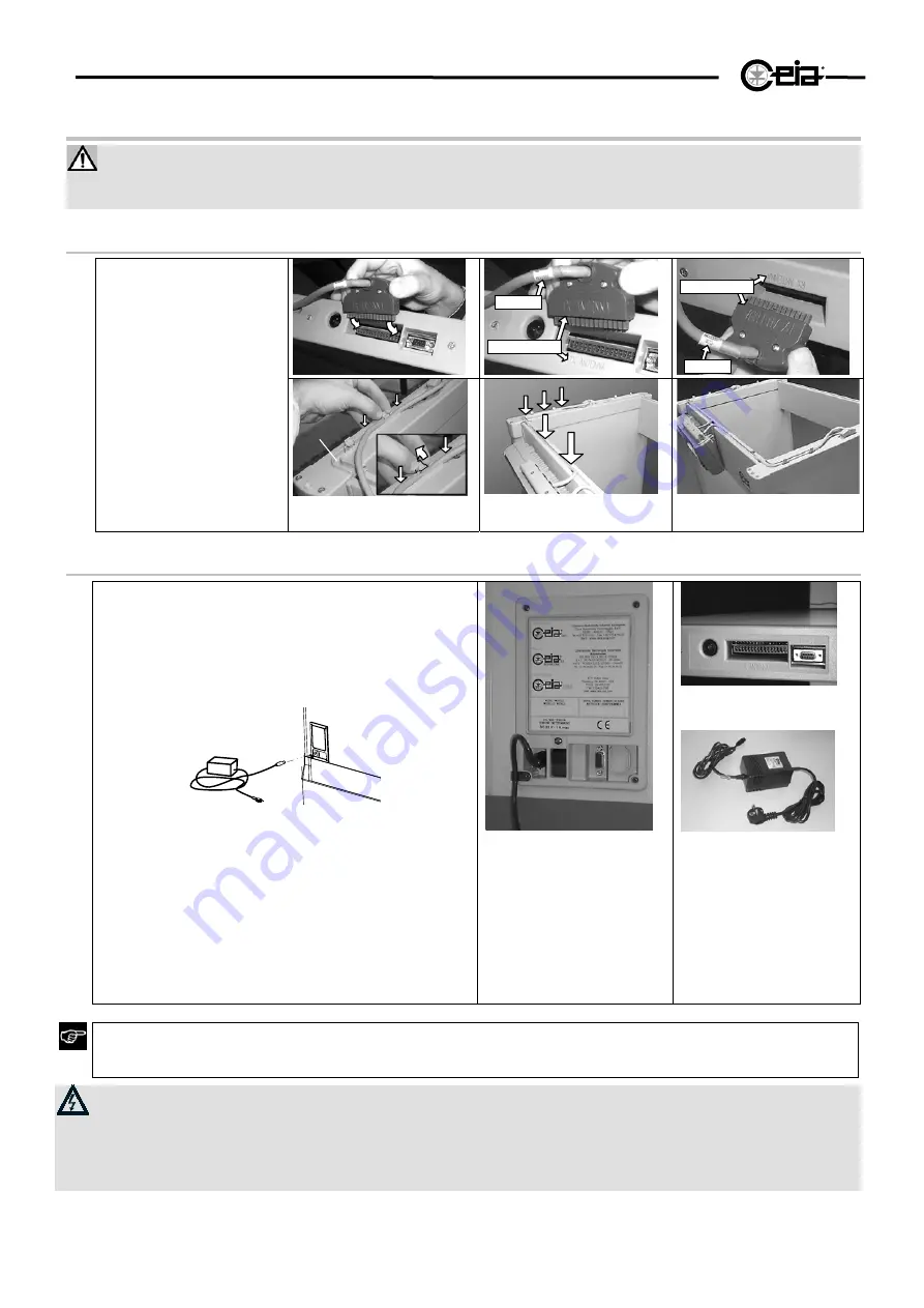
Connecting the electronics unit to the archway (antenna).
TX ANTENNA
60xxx
t
Ctx
RX ANTENNA
60xxx
r
Crx
•
Refer to figures II-1a
and II-1b.
The electronics unit is
fitted with two cables for
connection to the
antennae (
Crx
for the
receiver panel,
Ctx
for
the transmitter panel).
The connectors of the
receiver and transmitter
panels are located on
the top of the units.
•
Attach the cables to the
cross-bar using the
grooves (
cc
) provided.
cc
Fig. II-2c
Power supply connection
Refer to figures II-5a e II-5b.
The TX panel incorporates a low-voltage power-
supply section: the connection panel (
cp1
) is located
low down, and, in addition to the power-supply
connection socket
DC
, includes the connector for
serial communication (
B PORT
). The mains power
adapter
PSA
should be connected to connector
DC
.
ca
cp1
PSA
The connections panel is also designed for the
insertion of two emergency batteries (see Options
section).
The panel Metal Detector is provided with an
additional connection module located in the upper
part of the TX panel (
cp2
): this allows the
connections to be made via cables coming down
from the ceiling
.
B-PORT
L1
S1
DC
cp1
B-PORT
serial communication
port
cp1
lower
connection
module
DC
power-supply
cable
connector
L1
power indicator
S1
On/Off
switch
Fig. II-2d
T-PORT
TXc
DC
cp2
PSA
ca
ca
power supply cable
cp2
upper
connection
module
DC
power-supply
cable
connector
PSA
power supply adapter
T- PORT
serial communication
port
TXc
TX panel connector
for cable connecting
the control unit to the
TX panel
Check that the voltage supplied by the mains corresponds to the detector’s supply voltage: this latter is
indicated on the device’s power supply adapter and on the test report at the end of this booklet.
The use of a different mains voltage may damage the equipment
!
The standard power-supply adapter is not waterproof: place it in a well-ventilated position where it is protected
from water (rain, condensation, liquid detergents).
A protection switch should be connected up between the mains supply and the detector. The external
grounding line should conform to standards and should not in any case have a resistance greater than
3
Ohm
.
Auxiliary connections
: see appendix.


