background image


 HI-PE multi-zone --- Rev. 

FI 050 GB 60K10 v2_1


Installation, use and safety information 

READ THESE  INSTRUCTIONS BEFORE WORKING WITH THE DEVICE 

CEIA can not be held responsible for direct and/or indirect damage to persons and/or property arising 

from failure to observe these instructions.


Read this manual carefully before installing, operating or 
carrying out maintenance on the device. Keep this booklet in 
a safe place for future reference. 


Follow the instructions contained in this manual for all 
operations relating to installation, use and maintenance of the 
device. CEIA cannot be held responsible for any damage 
resulting from procedures which are not expressly indicated in 
this manual. 


The final user is responsible for selecting the appropriate 
security level/sensitivity for their application. After this 
selection has been made, and programming has been 
adjusted accordingly, it is also the final user's 
responsibility to verify calibration using the test object(s) 
appropriate to the level of security selected. Additionally, 
this test should be carried out periodically to insure no 
changes have occurred in the equipment. 


Whenever there is any suggestion that the level of protection 
has been reduced, the device should be taken out of service 
and secured against any possibility of unintentional use, and 
authorised service technicians should be called. 
The level of protection is considered to have been reduced 
when: 
- the device shows visible signs of deterioration; 
- the device does not operate correctly; 
- the device has been stored for a long period in sub-optimal 
conditions; 
- the device has suffered severe stress during transport; 
- the inside of the device has come into contact with liquids. 


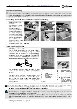
Choose the installation site carefully. Avoid placing the device 
in locations where it may be directly exposed to sunlight, in 
unventilated areas or in places that are close to sources of 
heat. In addition, avoid places that are subject to vibrations, 
dust, humidity, rain and excessively high or low  
temperatures. 


Installation must be carried out by qualified personnel. Given 
the dimensions of the device, it is requested that the 
installation site be kept clear while work is carried out to 
facilitate setting it up and to avoid any harm to third parties. 


Position the device as far away as possible from sources of 
electromagnetic interference such as transformers or motors. 


When installation is completed, the detector must be 
anchored to the ground in a stable manner and not subject to 
vibrations (use expansion screws inserted through the 
anchoring holes in the base of the panels). All connecting 
cables between the gateway and the power supply or other 
external devices must be properly fixed and protected so as to 
achieve the best performance from the detector and avoid 
accidental injury to people who might trip over them. 


Handle the device with care and without excessive force 
during installation, use and maintenance 


Before powering up the device, check that the mains power 
supply voltage corresponds to the voltage shown on the 
device's electrical specifications plaque.

 The use of a 

different mains voltage may damage the equipment!


The device should be connected to the mains voltage only 
after all the connections required for full installation have been 
carried out. 


The device must be connected to a power supply circuit fitted 
with a switch or other device which allows the power to be cut 
off. 


If the device is to be powered via an external autotransformer 
to regulate the voltage, ensure that the common terminal of 
the autotransformer is connected to the neutral of the power-
supply circuit.  


The power-supply plug must only be inserted into a socket 
fitted with an earth/ground connection. 
Any break in the safety conductor, either inside or outside the 
device, or disconnection of the earth/ground safety terminal, 
will render the device dangerous. Intentional cutting or 
disconnection is strictly forbidden. 


Always remove the plug by hand when disconnecting the 
power supply cable, never by  pulling on the cable. 


The standard power-supply adapter is not waterproof: place it 
in a ventilated position where it is protected from water (rain, 
condensation, liquid detergents)! There is a risk of electric 
shocks for people and damage to the equipment! 


This device contains electrical and electronic components, 
and may therefore be susceptible to fire. Do not install in 
explosive atmosphere or in contact with inflammable material. 
Do not use water or foam in the case of fire when the device 
is powered up. 


To prevent damage by lightning, disconnect the power supply 
cable during thunderstorms. 


Do not use in an explosive atmosphere. Avoid contact with 
inflammable or explosive material. 


Carry out the periodic maintenance regularly (see section on 
Maintenance). Do not wash the device with water, liquid 
detergents or chemical substances. Use a slightly moist, non-
abrasive cloth for cleaning. 


The device must be disconnected from all power sources 
before undergoing any maintenance or cleaning, and before 
being moved. 


Read the chapter on “Maintenance” carefully before calling 
the service centre. 
Whatever the problem, only specialised service personnel 
authorised to work with CEIA equipment should be called. 


Any damaged parts of the device should be replaced by 
original components only. 


Any maintenance or repair involving the device being opened 
while powered should be avoided as far as possible: if this 
becomes inevitable, the operation must be carried out only by 
qualified personnel who are fully aware of the risks involved. 


Important advice regarding any batteries incorporated in 
the device

. When replacing: use CEIA spare parts or 

batteries with equivalent electrical/mechanical characteristics. 
Do not dispose of used batteries in general rubbish bins; use 
public battery collection facilities as per local regulations, or 
return them to a CEIA office. If the equipment is to be 
disposed of, remove the batteries and dispose of them 
separately. CEIA will not hold itself responsible for the 
improper use of the batteries incorporated into its equipment: 
consult the battery manufacturer for more detailed 
information. 


Human exposure to electromagnetic fields. The equipment is 
pre-set in the factory according to the regulations applicable 
in the destination country. Any modification to this pre-setting 
is the responsibility of the installer. For further information 
contact the competent bodies. CEIA’s technical/sales 
department can provide further clarification.  

Summary of Contents for HI-PE multi-zone Series

Page 1: ...bed in the test report attached to the end of the manual itself Factory Acceptance Test Report These instructions are not generally applicable to equipment different from that described in the test re...

Page 2: ...quipment The device should be connected to the mains voltage only after all the connections required for full installation have been carried out The device must be connected to a power supply circuit...

Page 3: ...CEIA products extended to the period agreed with the Sales Department is applicable to goods supplied from our factory and for every constituent part thereof with the exception of the batteries and t...

Page 4: ...19 VISUAL ALARM ZONE INDICATION 20 STAND BY 21 IV PROGRAMMING 22 LOCAL PROGRAMMING 22 COMMAND EXECUTION LOCAL PROGRAMMING 22 Time out 23 DESCRIPTION OF THE COMMANDS 23 Reception Parameters 23 Transmis...

Page 5: ...e and adaptation to the user s requirements orientation towards ferromagnetic and or non magnetic metals This feature is particularly important in the detection of weapons made of light metal Immunity...

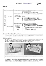
Page 6: ...tery 30 Photocells for transit counter Construction of the Metal Detector CEIA Metal Detectors are made up of an electronics unit and an archway antenna the connection between the two is via two cable...

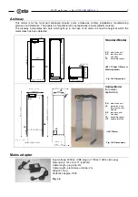
Page 7: ...55 88 3 4 50 2 630 24 3 4 6 5 1 4 t EU RX TX Standard Model EU electronics unit RX receiver panel t cross bar TX transmitter panel UW 720mm 760mm or 820mm optional Fig I 3a Dimensions t EU TX RX UP LP...

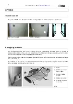
Page 8: ...event of a mains failure The batteries recharge automatically when the metal detector is connected to the AC power supply and switched on Use of the emergency batteries is signalled by a flashing let...

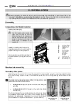
Page 9: ...L CA PL CA customer address EU electronics unit IK installation kit M manual PL list of materials RX receiver panel tr1 cross bar designed for fixing the electronics unit tr2 second cross bar TX trans...

Page 10: ...Configuration B TX on right Fig II 1b BD1 2 LED bar ca power supply cable cc central cable fixing groove CH chip card cp1 lower connection module cp2 upper connection module Crx RX panel electronics u...

Page 11: ...installation see paragraph Installation Check no signal or one green asterisk interference acceptable Fixing the antenna to the ground To fix the antenna to the ground screw the expansion screws vf i...

Page 12: ...ed for the insertion of two emergency batteries see Options section The panel Metal Detector is provided with an additional connection module located in the upper part of the TX panel cp2 this allows...

Page 13: ...PE multi zone Rev FI 050 GB 60K10 v2_1 13 Outdoor model for outdoor applications assembly A B C A upper protection B lower connection module protection C threaded knobs Kit composition B 1 2 3 A 4 A C...

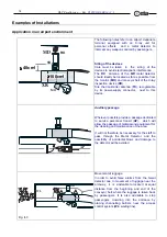
Page 14: ...ts power supply connector next to this device AP Auxiliary passage Wherever possible provide a passage dedicated to service personnel transit AP which will allow the passage of material and equipment...

Page 15: ...een the barriers and the probe of the metal detector MD1 XR OHT 2cm CEIA Personal Effects Depository We recommend placing a CEIA Personal Effects Depository OHT between the metal detector probe and th...

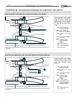
Page 16: ...Hand held metal detector CEIA PD140 Monitor of the X ray unit CEIA Personal Effects Depository Primary metal detector HI PE or 02PN10 Receiver antenna Transmitter antenna X ray unit High flow rate app...

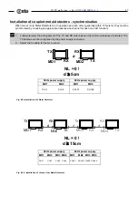
Page 17: ...and RX antennas and the minimum distances indicated The TX antenna can be recognised by the power supply connector 2 Select the 0 setting for the NL function TX RX MD1 RX TX MD2 d NL 0 d 5cm 50Hz pow...

Page 18: ...dicator S1 On Off switch Fig III 1b Detail of the lower connection module Display messages During operation the following messages may appear on the display see also AD command Programming section Ala...

Page 19: ...peration in line with standard NILECJ 0601 00 level 1 obtained via the IS International Security Standards function For the other possible settings see Programming section International security stand...

Page 20: ...arameter Fig III 6a alarm indication for a single metal mass Fig III 6b alarm indication for two metal masses Fig III 6c power indicator Three choices of operating mode floating standard 4 fixed zones...

Page 21: ...electronics unit display is off while the cp1 connection module LED indicator stays on enter the programming phase press ENTER enter password if defined SE 34 select PW function using the arrow keys P...

Page 22: ...s are scanned in a cyclical sequence SE DS LS This can occur in two directions by pressing the and keys Depending on how the metal detector is programmed only some of the commands may be displayed b S...

Page 23: ...ge metal masses 99 maximum sensitivity detection of small metal masses Z1 Z8 Zone sensitivity adjustment 99 99 C R In ZN 4 or ZN 8 mode selects the gain of the individual zone The rate of increase dec...

Page 24: ...m 9 maximum volume This determines the minimum value of the AV parameter In the standard settings this parameter can be accessed by the superuser only AT Alarm tone 0 9 C R 5 different continuous tone...

Page 25: ...ight from 0 to 99 continually updated To end measurement press any key If both GN and EN functions are activated function EN has priority EN Environmental electromagnetic noise measurement YES NO C Si...

Page 26: ...n will not be executed LD Loading stored parameters 1 10 C See function ST IS International Security Standard see the following table C R During normal operation the current Security Level is displaye...

Page 27: ...hts up at the height of transit of the metal mass 20 different zones of variable height and position 4 when a metal mass is detected one of 4 distinct zones each of fixed height and position lights up...

Page 28: ...al mass considered to be the smallest sample to be detected and make several passages through the probe The mass must be passed along the centre line of the archway changing the orientation of the sam...

Page 29: ...al detector can only count people passing through the gate if the correct value of GD is selected Proper operation of the photocells can be checked using the Autotest Programme See the Maintenance sec...

Page 30: ...e connections by linking telephone line PC personal computer MD1 MD2 metal detectors c1 cable for modem TL telephone line The archway is fitted with two connection modules one module in the lower part...

Page 31: ...pressed ENTER The syntax for the commands is strict If any non valid syntax is entered an error message will be sent by the Metal Detector Either upper or lower case characters can be used to enter co...

Page 32: ...nctions are available for the user see function UP At each programming level only the password relating to that same level can be modified The equipment is usually delivered from CEIA with a password...

Page 33: ...pear for user level for super user level Otherwise the password must be re entered After the third failed attempt to enter the password the device will pause for 10 seconds to avoid any computerised s...

Page 34: ...RE The alarm is kept in memory until the RE command is executed N B any reset button that might be connected to terminal PP1 will not have any effect A Mode corresponds to automatic reset the alarm s...

Page 35: ...arameters AA Alarm intensity indicator AC Alarm counter transits alarms and percentage of alarms on photocell models CI Number of inward transits CO number of outward transits GN Measurement of genera...

Page 36: ...check that all components of the metal detector are undamaged 4 months Visual inspection of connectors and power supply cables 4 months Floor anchoring inspection ensure that the archway is firmly anc...

Page 37: ...ng of data via the LD or IS commands from an unprogrammed memory cell Programme the memory cell ST command or use a pre programmed memory cell RS232 serial interface malfunction check the serial line...

Page 38: ...SA power adapter If the LED is on replace the ALP card Model with emergency batteries Flat batteries Connect the equipment to the mains supply and recharge the batteries Malfunction of ALP card Check...

Page 39: ...o nails or screws have been driven into the transducers move the metal detector away from the source eliminate the source of interference if the source consists of movement of large metal masses in th...

Page 40: ...tronics unit shows the signal PI PO see right without any object or person passing through the passageway the photocells do not see anything If the test is being carried out on a metal detector that i...

Page 41: ...lti zone Rev FI 050 GB 60K10 v2_1 41 Battery replacement procedure Necessary tools Medium size Phillips screwdriver PH1 Necessary items CEIA Spare batteries 2 pieces Fig VI 2 1 2 3 4 5 6 7 8 9 10 11 1...

Page 42: ...s r pond aux exigences de la Directive 73 23 CEE et aux modifications suivantes mentionn es dans la Directive 93 68 CEE concernant la basse tensions Dieses Produkt entspricht den Anforderungen an Nied...

Page 43: ...y Photocells monitoring of the transits through the gate optional J1 6 SER GND ground 5 PP1 Contacts PP1 SER GND on the J1 terminal board are connected to two photocells p1 p2 located on the antenna N...

Page 44: ...in outdoor applications or in particularly difficult environmental conditions The unit comprises two 12V 7Ah batteries and a charger and allows about 6 hours independent operation when mains power is...

Page 45: ...Code Cables connecting the antenna to the electronics unit 720mm cross bar 1 25034 Cable connecting the antenna to the electronics unit 820mm cross bar 1 25035 720mm cross bar with holes 1 24255 720mm...

Page 46: ...ss bar with holes 1 23470 760mm cross bar without holes 1 23471 Electronic card of the antenna luminous bar 1 21146 Photocell assembly 1 32824 Upper protection 1 23701 Threaded knob for the upper prot...

Page 47: ...HI PE multi zone Rev FI 050 GB 60K10 v2_1 47 Page intentionally left blank...

Page 48: ...HI PE multi zone Rev FI 050 GB 60K10 v2_1 48 www ceia net...

Reviews: