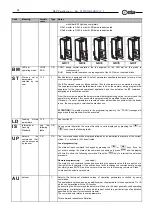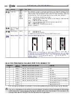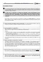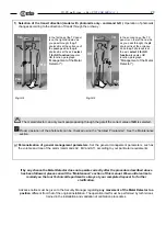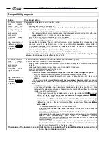
HI-PE multi-zone --- Rev.
FI 050 GB 60K10 v2_1
40
Procedures
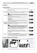
Autotest program
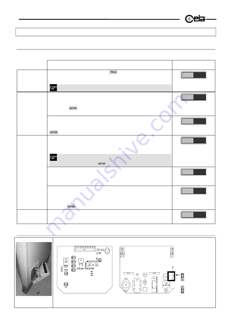
When the detector is switched on, a program may be run to test some of its components.
Operations to carry out
Display
Activating the
test
Turn on the detector and keep the
key of the central electronics
unit pressed down until the signal shown on the right appears .
the program can also activated by means of the PW command.
0 * 0 * 0 * 0 *
Test display
First phase
Checks correct functioning of all the segments of the display, which
should give the signal shown on the right.
Press the
key on the electronics unit keypad to go on to the
second phase.
0 * 0 * 0 * 0 *
Second phase
Checks the correct functioning of all the segments of the display,
which should now give the signal shown on the right. Press the
key of the electronics unit.
* 0 * 0 * 0 * 0
Photocell test
(if photocells
are installed)
The display of the electronics unit shows the signal: PI- PO- (see
right) without any object or person passing through the passageway:
the photocells do not "see" anything.
If the test is being carried out on a metal detector that is not fitted
with photocells, press
to pass to the next phase.
PI - PO-
Cover the first photocell relative to the direction of passage (see the
GD
function, Programming section). The display should indicate the
passage of an object through the entrance photocell (PI*).
PI * PO-
Cover the second photocell relative to the direction of passage.
The display should indicate the passage of an object through the exit
photocell (PO*).
Press the
key of the electronics unit.
PI - PO*
Voltage
The electronics unit display shows the DC voltage of the electronics
unit, updating the data continuously (in the example to the right,
31.8Vdc). The correct voltage levels are between 22 and 35 Vdc.
VIN=31.8
ALP card: trouble-shooting diagram
Fig VI-1 ALP card (with battery charger
J1,J3
battery connector
L1
on/off indicator
S1
on/off
switch
J6
RCU unit power
supply selector:
RCU activated
RCU deactivated

