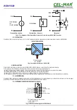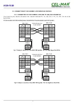
3.3. CONNECTION OF THE CURRENT LOOP INTERFACE DEVICES
3.3.1. CONNECTION OF THE CURRENT LOOP LINE TO ADA-1020 CONVERTER
The Current Loop line should be connected to the converter's terminals:TX+, TX-, RX+, RX- or TX+, TX-, RX+*, RX-, like on the
figures below.
On the converters with 0-20mA active/passive transmitter the TX switch should be set in ACT position
Fig 7. Example connection of two ADA-1020 together. The line length larger than 500m.
Fig 8. Example connection of two ADA-1020 together. The line length less than 500m.
7
ADA-1020
Current Loop Line
2-pair twisted
ADA-1020
Current Loop
Vss+
Vss-
Power
Supply
RS232
DCE/DB-9F
CTS -7
RTS -8
GND -5
Vss-
Vss+
Tx -2
Rx -3
DSR -4
DTR -6
Tx+
Tx-
Rx+
Rx-
Rx+*
Tx+
Tx-
Rx+*
Rx-
ADA-1020
Current Loop
Vss+
Vss-
Power
Supply
RS232
DCE/DB-9F
Tx -2
Rx -3
DSR -4
DTR -6
CTS -7
RTS -8
GND -5
Vss-
Vss+
Rx+

