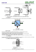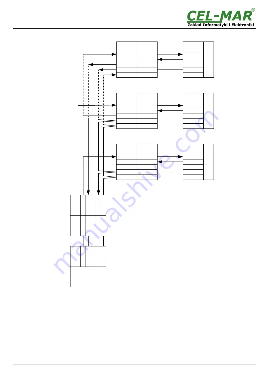
Fig 10. Example connection of ADA-1020 converters as Current Loop bus for 15 SLAVE converters
3.5.2. 3.5.1. CONNECTION OF 5 RS232 INTERFACE DEVICES TO CURRENT LOOP BUS
In this case/example the Current Loop bus is created by one ADA-1020 converter (MASTER
– active transmitter
) and one ADA-1020
converter (SLAVE
– active transmitter
- the furthest located from the MASTER) and max. 4 converters ADA-1020 (SLAVE –
passive
transmitter
). Connection made via Rx+* receiver terminal increases the resistance of the current loop receiver of overvoltage arising
Current Loop bus.
The number of the SLAVE converters can be less for long lines. Example of connection is shown below.
9
ADA-1020
G
N
D
R
S
23
2
C
u
rr
e
n
t
L
o
o
p
B
u
s
M
A
S
T
E
R
D
e
v
ic
e
M
o
d
em
G
S
M
.
.
R
x
T
x
S
L
A
V
E
-2
R
S
23
2
S
L
A
V
E
-1
5
R
S
23
2
RS232
Current Loop
ADA-1020-1-2-2-3
SLAVE-PASSIVE-1
S
L
A
V
E
-1
R
S
23
2
R
S
2
32
Rx+
Rx-
Rx+*
Tx+
Tx-
R
x-
T
x-
G
N
D
(
5)
R
x+
R
x+
*
T
x+
Rx+
Rx-
Rx+*
Tx+
Tx-
Rx+
Rx-
Rx+*
Tx+
Tx-
.
GND (5)
Tx (2)
Rx (3)
DB-9F
RS232
RS232
.
GND
Rx
Tx
RS232
.
T
x
(2
)
R
x
(3
)
R
S
2
32
D
B
9F
C
u
rr
e
n
t
L
o
o
p
A
D
A
-1
02
0
-1
-2
-2
-3
M
A
S
T
E
R
-A
C
T
IV
E
ADA-1020-1-2-2-3
SLAVE-PASSIVE-2
ADA-1020-1-2-2-3
SLAVE-ACTIVE-15
.
.
GND (5)
Tx (2)
Rx (3)
.
GND
Rx
Tx
.
GND (5)
Tx (2)
Rx (3)
.
GND
Rx
Tx
R
S
2
32
R
S
2
32
Current Loop
DB-9F
RS232
Current Loop
DB-9F
RS232

