background image

3.5. POWER SUPPLY CONNECTION

The power supply to the ADA-1021 converter should be DC (regulated) from 10 V= to 30V=. Nominal power is typically 2W, e.g. ZS-

12/250 or DR-15-24. Power cable from DC power supplies to device must not be longer than 3m. 

Observe the polarity, connect positive (+) of DC power supplies to V+ and negative (-) end to V- terminal. ADA-1021 has the protection

from opposite connection power supply. If after powering on the front panel is not lit green LED PWR, check the correctness of power

connection (polarity).

4. ACTIVATION

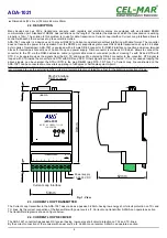
Converter can be powered after proper connection according to steps above. If the connection was made properly green LED PWR on

front panel  of  converter   should  lit,  if  not  check  polarization  of power  connection.  If  the  red LED RX is  lit  check  correctness  of

connection transmitting line of Current Loop Device. The lighting of RX LED indicates no current flow through the optocoupler in the

receiver's circuit.

During proper data transmission through converter  the LEDs Tx and Rx should blink.

4.1. LEDS DESCRIPTION

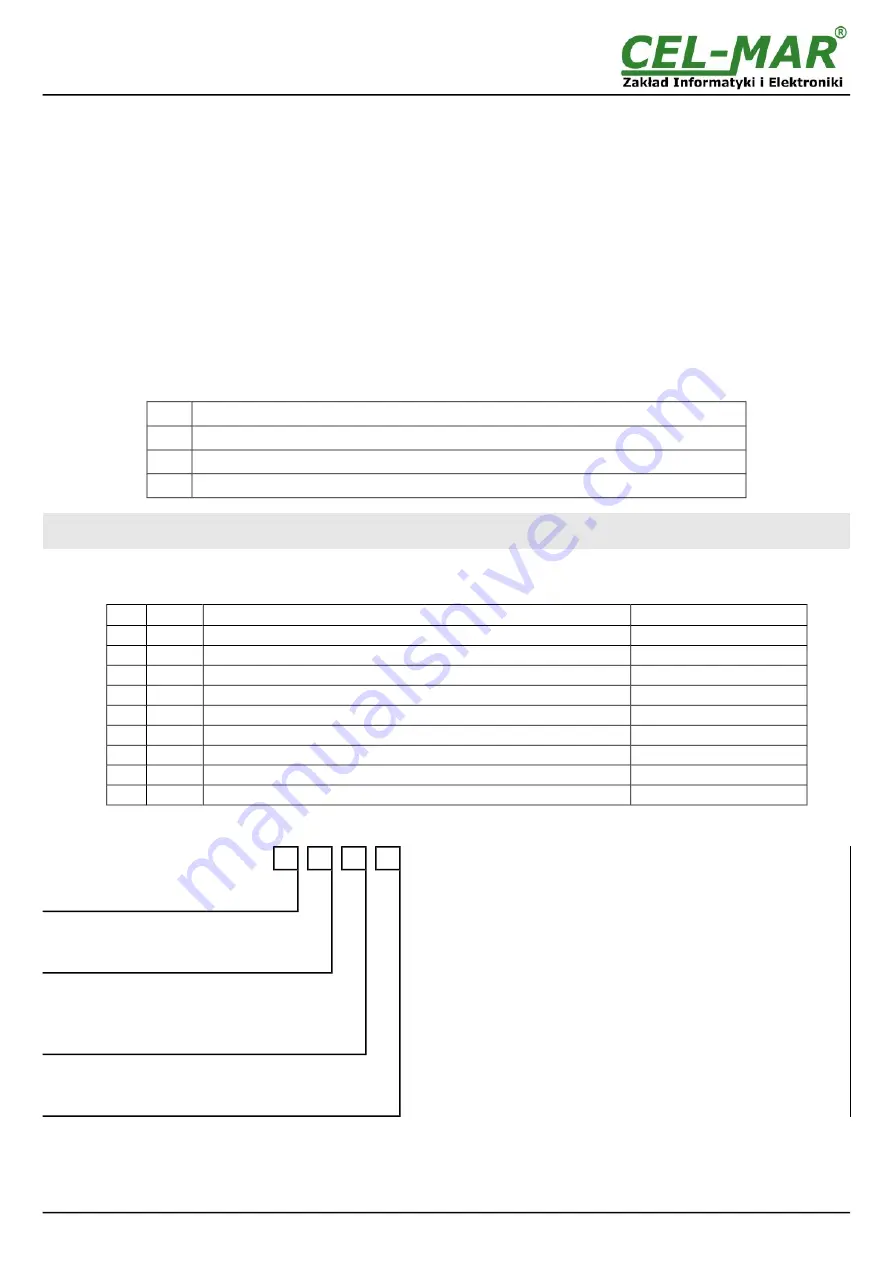
LED

Description

PWR Signalization of power supply

RX

Signalization of data receiving by  ADA-1021 from Current Loop.

TX

Signalization of data transmission from ADA-1021 converter through  Current Loop

ATTENTION!

AT BAUD RATE ABOVE 38.4 KBPS THE LED'S TX, RX WILL LIT WEAKLY DURING DATA TRANSMISSION

5. RS232 INTERFACE – PIN DESCRIPTION OF  DSUB-9F-DCE SOCKET

Pin

Signal

Description

ADA-1021

1 (DCD)

Level of receiver signal

Connected with DSR

2 (TxD) 

Data transmission from ADA-1021

Transmitter

3 (RxD) 

Data receiving from ADA-1021

Receiver

4 (DSR) 

Device readiness of data receiving/ transmission

Connected with DTR

5 (SG) 

Signal ground

GND

6 (DTR) 

ADA-1021 readiness of data receiving/ transmission

Connected with DSR

7 (CTS) 

The device confirms acceptance of the signal RTS from ADA-1021

Connected with RTS

8 (RTS)

ADA-1021 notify to the device readiness receiving data

Connected with CTS

9 (RI)

Call rate

Not connected

6. VERSIONS

ADA-1021 - 

-

-

-

Order example:

Product symbol: 

ADA-1021-1-2-1-2

1 – 

standard electronics version,

2 – 

current loop voltage12VDC,

1 – 

current loop current 0-20mA,

2 – 

galvanic isolation1kV=,

Electronics version:

Standard

1

Current Loop Voltage:

24VDC

1

12VDC (standard)

2

Current Loop Current:

0 – 20 mA (standard)

1

0 – 30 mA 

2

0 – 45 mA 

3

Galvanic isolation:

1kV= 3-way

2

3kV= 3-way

3

10

ADA-1021

Summary of Contents for ADA-1021

Page 1: ...User manual ADA 1021 RS 232 to Current Loop Converter 1 io_ada 1021_v1 02_en Copyright 2001 2017 CEL MAR sp j ADA 1021...

Page 2: ...ECTION OF DEVICES WITH RS232 PORT DCE TYPE MODEM 6 3 3 CONNECTION OF CURRENT LOOP DEVICES 7 3 3 1 CONNECTION TO DEVICE WITH PASSIVE TRANSMITTER PASSIVE RECEIVER 7 3 3 2 CONNECTION TO DEVICE WITH ACTIV...

Page 3: ...ps and the like Complete disable from the supply network is only after disconnecting the power supply circuit voltage Do not carry out the assembly or dis assembly of the device if it is enabled This...

Page 4: ...converter RTS signal is looped with CTS inside the converter and DTR with DSR and DCD Others signals are not connected If it is not needed looping the above signals can be unsolder the RTS or DTR in t...

Page 5: ...cables in the distance not shorter than 25 cm from powering cables apply cable of adequate cross section due to voltage drops for converter powering use Interference suppression filters for power supp...

Page 6: ...lable in CEL MAR offer Example connection is shown below Fig 6 Connection to device with RS232 type DCE 6 ADA 1021 RxD 2 TxD 3 DTR 4 DSR 6 RTS 7 CTS 8 PC SG 5 RS232 DTE DB 9M ADA 1021 Current Loop Vss...

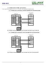
Page 7: ...with active transmitter and active receiver to ADA 1021 7 ADA 1021 ADA 1021 V V Power Tx Tx Rx Rx Current Loop Device I1 I1 I2 I2 Rx Current Loop connector Tx Tx Rx V V Active Transmitter Active Recei...

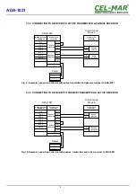
Page 8: ...21 ADA 1021 Active transmitter Power Tx Tx Rx Rx Current Loop Device I1 I1 I2 I2 Rx Passive receiver Tx Tx Rx Current Loop connector Current Loop connector V V V V Passive Receiver Active Transmitter...

Page 9: ...RTS 7 CTS 8 PC SG 5 RS232 DTE DB 9M ADA 1020 Current Loop Vss Vss Power Supply RS232 DCE DB 9F CTS 7 RTS 8 GND 5 V V Tx 2 Rx 3 DSR 4 DTR 6 2 3 4 6 7 8 5 CAB DB 9F DB9M S 1 8m cable Socked DB 9F 2 3 4...

Page 10: ...PWR Signalization of power supply RX Signalization of data receiving by ADA 1021 from Current Loop TX Signalization of data transmission from ADA 1021 converter through Current Loop ATTENTION AT BAUD...

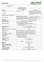
Page 11: ...ow LED data transmission through Current Loop interface Electrical Parameters Power requirements 10 24 30 V DC Power cable Recommended length of power cable 3m Power 3W Protection from reverse power p...

Page 12: ...transmission converters with interface RS232 RS485 RS422 USB Current Loop Fibre Optic Converters and Ethernet or Wi Fi Please contact us to tell how you like our products and how we can satisfy you p...

Reviews: