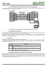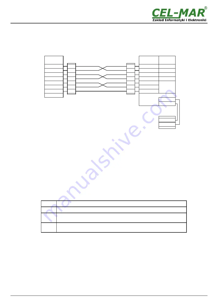
3.2.2. CONNECTION OF DEVICES WITH RS232 PORT - DCE TYPE (MODEM)
To connect the ADA-1028L to device with DCE (eg Modem) RS232 port type, is required RS232 cable CAB-DB9M/DB9M-C-1,8m
available in our offer. Connection example is shown below.
Fig 6. DCE type connection of ADA-1028L to device with RS232 interface (eg. modem)
3.3. POWER SUPPLY CONNECTION
The power supply to the ADA-1028L converter should be DC (regulated) from 10 V= to 30V=. Nominal power is typically 2W, e.g.
HDR-15-24. Power cable from DC power supplies to device must not be longer than 3m.
Observe the polarity, connect positive (+) of DC power supplies to V+ and negative (-) end to V- terminal. ADA-1028L has the
protection from opposite connection power supply. If after powering on the front panel is not lit green LED PWR, check the
correctness of power connection (polarity).
4. ACTIVATION
Converter can be power on after proper connection according to steps above.
If connection was made properly green LED PWR on front panel of converter should light, if not check polarization of power
connection and if RX LED is lighted check correctness of connection of Current Loop transmitter circuit. When data is present the
LEDs Tx and Rx should blinking.
LED
Description
PWR
Signalling of Power Supply
RX
Signalling of data receiving through ADA- 1028L converter from Current Loop CLO
port.
TX
Signalling of data transmitting from ADA- 1028L converter through Current Loop CLO
port. (the LED goes out during data transmission)
4.1. SENSITIVITY SETTING OF CLO CURRENT LOOP RECEIVER
Devices with a passive interface CLO may have different current values in the logical zero state, therefore should be set a converter
receiver sensitivity. Wrong adjustment of receiver sensitivity is revealed by not lit of RX LED during data receiving from connected
devices (energy counter) despite the correct connections to converter. A sensitivity is set by adding additional resistor to Rd and
CLO+ screw terminal block. If the resistor is correct RX LED will be blinking during data receiving. ADA-1028L converter is supplied
with resistors Rd = 220
W
/ 0,25W and 120
W
/ 0,25W.
7
ADA-1028L
RxD - 2
TxD - 3
DTR - 4
DSR - 6
RTS - 7
CTS - 8
Device with RS232
port DCE type
SG -5
RS232
DTE/DB-9M
ADA-1028L
CLO
V +
V -
Power
RS232
DCE/DB-9F
CTS -7
RTS -8
GND -5
Vss-
Vss+
Tx -2
Rx -3
DSR -4
DTR -6
CLO +
NC
Rd
2
3
4
6
7
8
5
CAB-DB9M/BD9M-C-2m /
ADP-DB9M/DB9M-C
Cable / Adapter
DB-9F
socked
2
3
4
6
7
8
5
DB-9M
plug
CLO -
Summary of Contents for ADA-1028L
Page 10: ...10 ADA 1028L...
Page 11: ...11 ADA 1028L...

