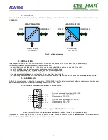
2.4. ISOLATION
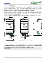
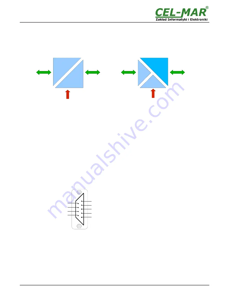
Converter ADA-1040 has 2-way or 3-way and 1kV= or 3kV= galvanic isolation (depend on version), this will be described in section
VERSIONS.
Fig 3. Isolation structure
3. INSTALLATION
This chapter will show how to connect ADA-1040 to RS485/422 bus, devices with RS232 interface and power supply.
To reduce disturbance from environment, it is recommended to:
–
use multipair type shielded cables, which shield can be connected to the earthing on one end of the cable,
–
use the suitable diameter cable for power supply on account of voltage drop,
–
use the powering cable with a suitable section because of the voltage drops,
–
use the interference eliminators for powering the converter,
–
lay signal cables at a distance of not less than 25 cm away from power cables,
–
not powering the converters form the power-circuit of devices generate large impulse disturbance like contactors, relays, inverters.
3.1. ASSEMBLING
ADA-1040 converter case is adapted to assembly on TS-35 (DIN35) rail. To install converter should mount device on the rail upper
part of the case then press bottom part to hearing characteristic „Click” sound.
3.2. CONNECTION OF DEVICES WITH RS232 PORT
Fig 4. RS232 interface signals of DB-9F (female) connector.
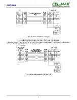
3.2.1. CONNECTION OF DEVICES WITH RS232 PORT - DTE TYPE (COMPUTER)
In purpose of connecting ADA-1040 to RS232 port of computer, should be used the RS232 extension cable CAB-DB9F/DB9M-S-
1,8m (available in CEL-MAR offer). Example connection is shown below.
5
ADA-1040
Power Supply
10 - 30VDC
RS232
RS485/RS422
Power Supply
10 - 30VDC
RS485/RS422
R232
3-WAY ISOLATION
2-WAY ISOLATION
4 DSR
For version without additional signals DTR,DSR :
1. Connected are DTR – DSR – DCD
2. Connected are RTS – CTS
For version with additional signals DTR, DSR :
1. Connected are DTR – DCD
2. Connected are RTS - CTS
2 TX
5 GND
RI 9
RTS 8
CTS 7
DTR 6
3 RX
1 DCD

