background image

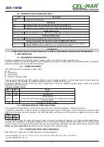
6.5. EMERGENCY FIRMWARE UPDATE

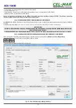
In case of the unsuccessful update of the converter software, try again according to description in point FIRMWARE UPDATE If the
update is still incorrect use emergency firmware update. Set SW1 microswitch mode as in the table below.

SW1-1

SW1-2

OFF

ON

After micro-switch setting, should be restarted the ADA-1040D, by turning OFF and then ON the power supply. The yellow LED will
light continuously and the converter will  be in Emergency Firmware Update mode. Now follow the description in point FIRMWARE
UPDATE.

ATTENTION!

AFTER SUCCESSFUL UPDATING SET SW1 

SW1-1

SW1-2

OFF

OFF

6.6. FACTORY DEFAULT

In case of faulty functioning the ADA-1040D, can be restored the factory default setting. Set SW1 microswitch mode as in the table
below

SW1-1

SW1-2

ON

OFF

Disconnect the power and after while connect again. After that, will be loaded the factory default setting. Parameters are as follows:

RS232

RS485(4W) / 422

Baud rate 9600 bps

Baud rate 19200 bps

8 data bits

8 data bits

none parity control

parity control

1 stop bit

1 stop bit

After this operation should return to run mode by setting micro- switch section of SW like in table below.

SW1-1

SW1-2

OFF

OFF

The yellow LED will be OFF.

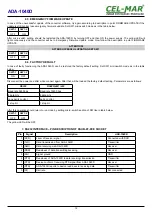
7. RS232 INTERFACE – PIN DESCRIPTION OF DSUB-9F-DCE SOCKET

Pin

Signal

Description

ADA-1040D

1 (DCD)

Level of receiver signal

Connected with DSR

2 (TxD) 

Data transmission from ADA-1040D

Transmitter

3 (RxD) 

Data receiving via ADA-1040D

Receiver

4 (DSR) 

Readiness of data transmitting/receiving

Receiver

5 (SG) 

Signal ground

GND

6 (DTR) 

Readiness of ADA-1040D to data receiving/ transmission

Transmitter

7 (CTS) 

Device confirm of receiving RTS signal from ADA-1040D

Receiver

8 (RTS)

ADA-1040D reports to device readiness to receiving data

Transmitter

9 (RI)

Call rate

Not connected

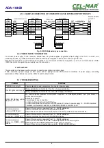
12

ADA-1040D

Summary of Contents for ADA-1040D

Page 1: ...User manual ADA 1040D RS 232 to RS 485 4W RS 422 digital converter 1 io_ada 1040d_v1 11_en Copyright 2001 2020 CEL MAR sp j ADA 1040D...

Page 2: ...7 4 3 1 GND TERMINAL CONNECTION 7 4 3 2 LINE TERMINATION Rt 7 4 3 3 EXAMPLE CONNECTION OF CONVERTER AS THE EXTENSION PORT RS232 PC 8 4 4 POWER SUPPLY CONNECTION 8 5 ACTIVATION 8 5 1 TROUBLESHOOTING 8...

Page 3: ...assembly or disassembly of the device if it is enabled This may result to short circuit and damage the device The device can not be used for applications that determine human life and health eg Medic...

Page 4: ...bus is made by the use of 2 pairs twisted cable The converter has the connection control for testing the correctness connection of RS485 4W bus with him ADA 1040D is equipped with DSUB 9 female conne...

Page 5: ...s of using the converter as extender of RS232 PC port Fig 3 Operating principle of ADA1040D Fig 4 Example connection of a cash register with RS232 interface to PC 1200 m away 5 ADA 1040D Cash register...

Page 6: ...MBLING ADA 1040D converter case is adapted to assembly on TS 35 DIN35 rail To install converter should mount device on the rail upper part of the case then press bottom part to hearing characteristic...

Page 7: ...tallation signals grounds of other devices 4 3 2 LINE TERMINATION Rt The application of Line Termination terminator Rt 120 W ohms will reduce electrical reflection in data line at high baud rate It is...

Page 8: ...onnection is there no break or short circuit of the bus is there connected the converter on the other side of the bus to power supply 10 30VDC stabilized are there set the same baud rate on RS485 4W R...

Page 9: ...riate settings by the use a small flat screwdriver All available adjusting the SW1 switch are shown in table below If there are additional question please contact with technical department 48 41 362 1...

Page 10: ...smission parameters to the length of RS485 422 bus Available baud rates kbps 0 3 0 6 1 2 1 8 2 4 4 8 7 2 9 6 14 4 19 2 28 8 38 4 57 6 76 8 115 2 230 4 ATTENTION IN BOTH CONVERTERS CREATING CONNECTION...

Page 11: ...onverter ports After finishing the diagnostics the SW1 microswitch should be set to the run mode as shown in the table below SW1 1 SW1 2 OFF OFF The yellow LED located near the SW1 will turn off 6 4 F...

Page 12: ...t the power and after while connect again After that will be loaded the factory default setting Parameters are as follows RS232 RS485 4W 422 Baud rate 9600 bps Baud rate 19200 bps 8 data bits 8 data b...

Page 13: ...EIA 485 CCITT V 11 Max baud rate 230 4 kbps Transmission type Asynchronous full duplex half duplex Optical Signalization PWD green LED power supply RX red LED data receiving on RS485 RS422 TX yellow L...

Page 14: ...According to standards DIN EN50022 DIN EN43880 Location during work Free Mounting Rail mounting according to DIN35 standard TS35 14 ADA 1040D...

Page 15: ...15 ADA 1040D...
Page 16: ...transmission converters with interface RS232 RS485 RS422 USB Current Loop Fibre Optic Converters and Ethernet or Wi Fi Please contact us to tell how you like our products and how we can satisfy you pr...

Reviews: