background image

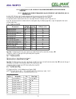
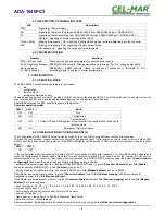
4.1. DESCRIPTION OF SIGNALLING LEDS 

LED

Description

PWR

Signalling of Power Supply

RX

Signalling of data receiving through ADA-1040PC3 from RS485/RS422 port – MODBUS-RTU

TX

Signalling of data transmitting from ADA-1040PC3 through RS485/RS422 port – MODBUS-RTU

Yellow LED by 

SW1

Not light – signalling of normal operating mode (RUN)
Blinking at frequency 1 Hz - signalling of configuration mode or software data flowing to the converter
Blinking at frequency 2 Hz - signalling of factory default mode
Lit continuously – signalling of emergency firmware update

4.2. TROUBLESHOOTING

Problem

Solutions

PWR LED is not light

Check polarization and parameters of connected power supply.

Rx LED lights continuously RS485(4W) /422 network. Wrong polarization on terminals: Rx+, Rx-; change polarization.
No transmission

Tx LED is blinking

RS485(4W)   /   RS422   network.   Check   correctness   of   connection   to   terminals   Tx,   Rx;

according to point 3 and the converter configuration.

5. CONFIGURATION 

5.1. OPERATION MODE

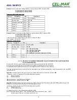
The ADA-1040PC3 converter can operates in a few modes :

run,

configuration,

factory default,

emergency firmware update

Those modes can be set by use SW1 located by DB-9F connector, labelled as RS232. To set the switch section, should remove the

cover marked as SW1 and make the appropriate settings by the use a small, flat screwdriver. 

All available adjusting the SW1 switch are shown in table below.

Converter operation modes

SW1- 1

SW1- 2

Mode

OFF

OFF

Run

ON

OFF

Configuration

OFF

ON

Factory default

Turning OFF and ON the power of the converter, the configuration will be set to

factory default.

ON

ON

Emergency Firmware Update

5.2. CONFIGURATION BY USING ADACONFIG

The configuration of ADA-1040PC3 converter can be made by the use of 

ADAConfig

 Software - selling with converter.

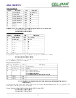
To make the configuration, connect converter to computer and power supply.  If after power, on the front panel is not lit green LED

PWR, check the power connection (polarity). If the PWR LED lights, set the section of SW1 switch to configuration mode as in table

below.

SW1-1

SW1-2

ON

OFF

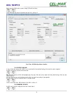
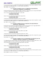
In the configuration mode the yellow LED located by SW1 micro-switch will blink with frequency 1 Hz. Start ADAConfig Software and

make the configuration of transmission parameters for  each converter interfaces. First, should be set the number of COM port for
communication with the converter, then readout the configuration from ADA-1040PC3 memory using the button  

[Read converter

configuration]

 and make the proper changes of each interfaces setting, as below:

– setting of the converter address from the side of RS485 MODBUS-RTU bus - in group [

Converter Address

] select field [

Enable

]

and enter address MODBUS-RTU in field [

Address

] (scope 1-247),

– setting of address SunMaster inverter, connected to RS232 port, field [

Mapped address

] (scope 16-65535),

If SunMaster inverter address is known, in group [

Converter Address

] select field [

Address mapping

] and enter address of

SunMaster inverter in the field [

Mapped address

].

If SunMaster inverter address is unknown, in group [

Converter Address

] unselect field [

Address mapping

] and in the field [

Mapped

address

] don't enter any data.

– baud rate (kbps): 0.3, 0.6, 1.2, 1.8, 2.4, 4.8, 7.2, 9.6, 14.4, 19.2, 28.8, 38.4, 57.6, 76.8, 115.2, 230.4,

– number of data bites: 5, 6, 7, 8,
– control parity: no control, parity control, control of none parity,
– number of stop bits : 1, 2,
– frame spacing – range from 4 to 255 (time silence as frame's end),

– data flow control – not available yet.
After configuration, the setting should be saved on converter memory by using button 

[Write converter configuration].

9

ADA-1040PC3

Summary of Contents for ADA-1040PC3

Page 1: ...User manual ADA 1040PC3 SunMaster to MODBUS RTU converter 1 io_ada 1040pc3_v1 06_en Copyright 2001 2017 CEL MAR sp j ADA 1040PC3...

Page 2: ...8 1 2 REGISTERS ACTUAL VALUES MEASUREMENTS AND CONDITION INVERTER READOUT BY FUNCTION 03 4X REFERENCES HOLDING REGISTERS 14 8 2 FRAME STRUCTURE OF MODBUS RTU PROTOCOL 14 8 3 USED FUNCTIONS OF MODBUS R...

Page 3: ...to short circuit and damage the device The device can not be used for applications that determine human life and health eg Medical 1 3 CE LABEL The CE symbol on the device CEL MAR means compatibility...

Page 4: ...and support the asynchronous transmission data with baud rate 230 4 kbps ADA 1040PC3 has DB 9F connector for connecting PC Link RS232 interface to Soladin and screw terminal block for connection of RS...

Page 5: ...ables in the distance not shorter than 25 cm from powering cables apply cable of adequate cross section due to voltage drops for converter powering use suppression filters for powering converters that...

Page 6: ...x PC or RS232 device 5 2 3 GND Tx A Tx B Rx Rx ADA 1040PC3 Tx 2 Rx 3 GND 5 5 2 3 DB 9F socket RS485 422 connector DB 9F RS232 connector DB 9M plug RS cable DB 9M RS232 connector USB DB 9M RS232 connec...

Page 7: ...ON OF INVERTER WITH SOLADIN INTERFACE TO RS485 4W MODBUS RTU BUS Fig 7 Example connection of SOLADIN inverter by the use of ADA 1040PC3 to RS485 4W 4 wire bus 7 ADA 1040PC3 RS485 RS422 connector RS485...

Page 8: ...0 W 5 0 25W are delivered with the converters 3 6 POWER SUPPLY CONNECTION To connect power supply to the converter should have DC power supplies regulated output voltage from 10 V to 30V min nominal p...

Page 9: ...DA 1040PC3 converter can be made by the use of ADAConfig Software selling with converter To make the configuration connect converter to computer and power supply If after power on the front panel is n...

Page 10: ...ode as in the table below SW1 1 SW1 2 OFF ON Disconnect the power and after while connect again the power After that will be loaded the factory default setting to the converter internal registers Afte...

Page 11: ...t continuously and the converter will be in Emergency Firmware Update mode Now follow the description in the above point After successful software update set microswitch SW1 to the run mode as shown i...

Page 12: ...ace should connect to RS485 RS422 port RS485 MODBUS RTU bus Frames of MODBUS protocol having the errors CRC are rejected by the converter Frames of SunMaster Soladin having the errors CRC are also rej...

Page 13: ...atus R 16 bit register 30003 2 UsolH UsolL 16 bit solar panel voltage DC measurement R 16 bit register 30004 3 IsolH IsolL 16 bit solar panel current DC measurement R 16 bit register 30005 4 FacH FacL...

Page 14: ...16 bit network power measurement AC R 16 bit register 40009 8 Hi 0x00 EacH Low R 16 bit register 40010 9 EacM EacL 24 bit energy counter kWh R 16 bit register 40011 10 TempH 0x00 TempL 8 bit inverter...

Page 15: ...n h 60 Time from reclosing Trec s 1 Network impedance measurement Rac W 100 Algorithm 1 Readout register is saved to regular type variable float and then divide it by the factor DW Fragment of code in...

Page 16: ...ion 0x03 0x04 are used for readout of status and measurement values from the INVERTER The measurement values readout form MODBUS RTU register is presented by two 16 bit registers The registers with th...

Page 17: ...work energy meter Eac from registry address 40009 address 30009 11 03 04 00 00 0B 90 CRCLo CRCHi 11 04 04 00 00 0B 90 CRCLo CRCHi In respond the value of AC network energy meter Eac is presented as 4...

Page 18: ...NCY VALUE Fac ALTERNATING VOLTAGE NETWORK CONNECTED TO INVERTER 4X 3X REFERENCES The measurement value of frequency alternating voltage network to inverter readout from 16 bit register Fac MODBUS RTU...

Page 19: ...in C C type short int Query of inverter power network Pac from registry address 40008 address 30008 11 03 00 07 00 01 CRCLo CRCHi 11 04 00 07 00 01 CRCLo CRCHi Readout of inverter power network Pac f...

Page 20: ...nverter s running time Ton from registry address 40012 address 30012 11 03 00 08 0B 02 CRCLo CRCHi 11 04 00 08 0B 02 CRCLo CRCHi Readout of inverter s running time Ton from registry address 40012 addr...

Page 21: ...O 1 YES 6 Network frequency Fac Low 0 NO 1 YES 7 Inverter on 0 NO 1 YES 7 Inverter temperature High 0 NO 1 YES 9 RS232 INTERFACE PIN DESCRIPTION OF DSUB 9F DCE SOCKET Pin Signal Description ADA 1040PC...

Page 22: ...yellow LED data transmission through RS485 RS422 interface Electrical Parameters Power requirements 10 24 30 V DC Power Cable Recommended length of power cable up to 3m Power 2W Protection from rever...

Page 23: ...23 ADA 1040PC3...
Page 24: ...munications products in the world such as data transmission converters with interface RS232 RS485 RS422 USB Current Loop Fibre Optic Converters and Ethernet or Wi Fi Please contact us to tell how you...

Reviews: