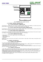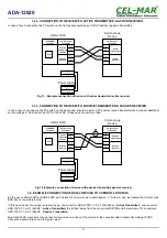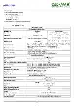
3.3.2. CONNECTION TO DEVICE WITH ACTIVE TRANSMITTER & ACTIVE RECEIVER
In case of such connection the TX switch on the front panel should be set to PSV position (passive transmitter).
Fig 11. Example connection of device with active transmitter/ active receiver
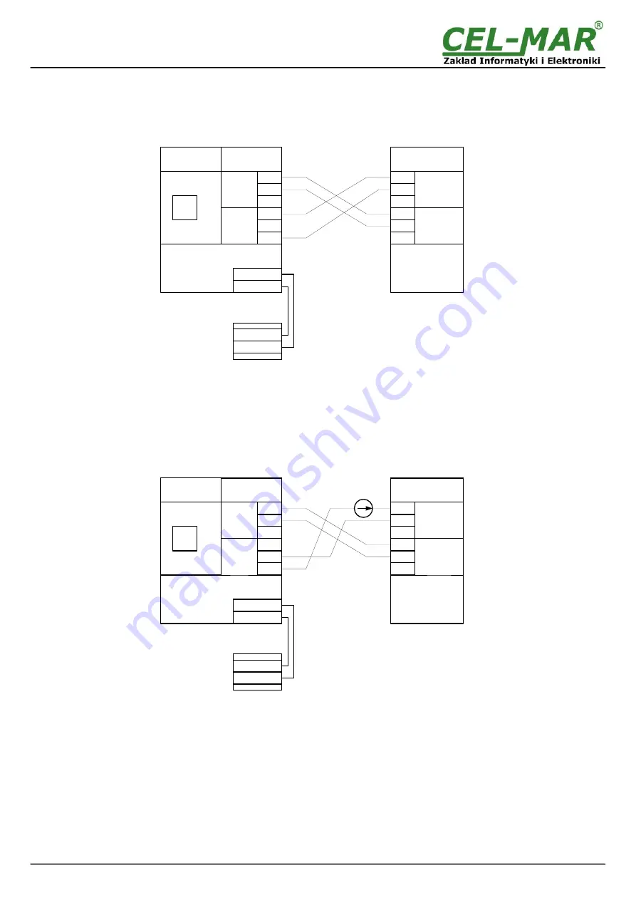
3.3.3. CONNECTION TO DEVICE WITH PASSIVE TRANSMITTER & PASSIVE RECEIVER
In case of such connection the TX switch on the front panel should be set to ACT position (active transmitter) and connect additional
source voltage U, from the scope 12VDC to 24VDC – depend on converter version.
Fig 12. Example connection of device with passive transmitter/ passive receiver
3.4. EXAMPLE CONNECTION OF RS232 DEVICES TO CURRENT LOOP BUS
By the use of ADA-13020 and ADA-1020, with Current Loop version as Active/Passive, I= 0-20 mA, can be created the Current Loop
BUS like on the picture below.
In this case Current Loop bus is created by eg. one converter ADA-13020-1-1-2-2-3 (MASTER –
Active Transmitter
), one converter
ADA-1020-1-1-2-2-3 (SLAVE -
Active Transmitter)
the furthest away from the converter MASTER and a maximum of 14 converters
ADA-1020-1-1-2-2-3 (SLAVE -
Passive Transmitter
).
Quantity SLAVE converters may be less for long lines or in case of the version of the converter with a transmitter voltage 12VDC.
Connection example is shown in Figure below.
11
ADA-13020
ADA-13020
Active
Transmitter
V+
V-
ETH
V-
V+
Tx+
Tx-
Rx+
Rx-
Tx+
Tx-
Rx+
Rx-
Rx+*
Active
Receiver
Passive
Transmitter
TX=PSV
Passive
Receiver
Power supply
Current Loop
Device
Current Loop
connector
ETHERNET
connector
Current Loop
connector
ADA-13020
Passive
Transmitter
V+
V-
ETH
V-
V+
Tx+
Tx-
Rx+
Rx-
Tx+
Tx-
Rx+
Rx-
Rx+*
Passive
Receiver
Active
Transmitter
TX=ACT
Passive
Receiver
U
Power supply
Current Loop
Device
Current Loop
connector
ETHERNET
connector
Current Loop
connector


