background image

6. USING VIRTUAL PORT SERVICE [REALPORT] 

6.1. VIRTUAL PORT DRIVER INSTALLATION IN  WINDOWS XP

The installation of virtual serial port drivers should be done for the CD, by choosing: 

Win Server-2003-2008-2012

Win-2000

Win-98-ME

Win-NT4.0SP5

Win-Vista

Win-XP-7-8

Installation of Virtual serial port drivers is as follow:

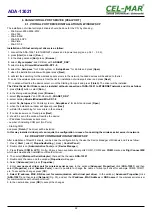
1. connect the ADA-13021 to ETHERNET network and to power supply (see p.3.2.1 - 3.2.2.),
2. press [

Start

] and select [

Run...

],

3. in the dialog window [

Run

] press [ 

Browse 

],

4.

select „

My computer

” and CD-Rom with „

ADANET_DRV

”,

5.

select catalog 

Drivers/Windows/Win-XP-7-8,

6.

select file „

Setup.exe

” for 32-bits system or „

Setup64.exe

” for 64-bits and press [

Open

],

7. when the installation window will appear press [

Next

],

8. will start the searching for the wireless serial servers in the network, founded devices will be added to the list.

9.

 select the wireless serial servers from the list for installation of virtual port driver and press [

Next

].

10.

 in window Describe the device select or not the Starting Com port and press [

Finish

]. The driver will be installed.

The Virtual Serial Port Drivers can be installed without connection of ADA-13021 to ETHERNET network and it is as follow:

1.

press [

Start

] button, select [

Run...

]

2. in the dialog window [

Run

] press [ 

Browse 

]

3. select „

My computer

” and CD-Rom with „

ADANET_DRV

”.

4. select catalog 

Drivers/Windows/Win-XP-7-8

.

5. select file „

Setup.exe

” for 32-bits system or „

Setup64.exe

” for 64-bits and press [

Open

].

6. when the installation window will appear press [

Next

] .

7. will start the searching for converters in the network.
8. if no devices were not found press [

Next

].

9. should be set in the window Describe the device:
– IP address for wireless serial server,
– number of installing COM port (No. Ports)
– Starting COM
and press [

Finish

]. The driver will be installed.

In this way installed virtual port can require the configuration in case of connecting the wireless serial server to network.

6.2. REALPORT CONFIGURATION IN WINDOWS XP

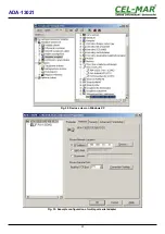
After installation of RealPort drivers, can be done the configuration by the use the Device Manager of Windows and it is as follow:
1. Press [ 

Start 

], select [ 

Properties/Setting 

], press [ 

Control Panel 

].

2. Double click icon [ 

Administrative Tools

] and [ 

Device Manager 

]

3. Press [

Ports (COM & LPT)

]. On fig. 29 are shown available serial ports COM1, COM2 and 

COM3 

marked as 

Digi Connect ME

which was created after installation of RealPort driver.
4. Then select [

Multi-port Serial Adapter

], there will be the name 

ADA-13021 

.

5. Double click the name and the window [

Properties

] will appear.

6. Select [

Advanced

] and press [

Properties

].

7. Enter  

new name of virtual port for wireless serial server

. In the window [

Advanced Properties

] click [

ADA-13021

] and then

select [

Properties

], press [

Rename Ports

], now it is possible to change the name of virtual port driver for example COM5, COM11

etc. To accept the changes press [

OK

].

8. 

Select IP address, MAC, DNS server for communication with virtual port driver

. In the window [ 

Advanced Properties

] click

[

ADA-13021

] and then select [

Network

] (Fig. 30), and set the 

IP address

MAC Address 

or 

DNS name

 of the wireless serial server

for communication with virtual port driver.
9. In the next window press [

OK

] to accept the changes.

22

ADA-13021

Summary of Contents for ADA-13021

Page 1: ...User manual ADA 13021 ETHERNET to Current Loop converter 1 io_ada 13021_v1 07_en ADA 13021 Copyright 2001 2020 CEL MAR sp j...

Page 2: ...ARE 12 5 1 1 ADAFINDER INSTALLATION 12 5 1 2 NETWORK SETTING 12 5 2 CONFIGURATION AND MANAGEMENT BY THE USE OF INTERNET BROWSER 14 5 2 1 NETWORK CONFIGURATION 14 5 2 2 SERIAL PORT CONFIGURATION 15 5 2...

Page 3: ...6 1 VIRTUAL PORT DRIVER INSTALLATION IN WINDOWS XP 22 6 2 REALPORT CONFIGURATION IN WINDOWS XP 22 7 FACTORY DEFAULT 24 8 PROBLEMS 24 9 VERSIONS 24 10 SPECIFICATION 25 3 ADA 13021...

Page 4: ...Do not put the fire opened on device sources candles an oil lamps and the like Complete disable from the supply network is only after disconnecting the power supply circuit voltage Do not carry out t...

Page 5: ...was made on base safety diodes and fuses on each Current Loop lines To Current Loop interface can be connected one device in point to point topology operates in half duplex or full duplex mode This co...

Page 6: ...eceiver broken connection of transmitter to receiver The diagram is shown on figure below Fig 3 Diagram of the transmitter receiver ADA 13021 Current Loop 2 5 ISOLATION Converter ADA 13021 has 3 way g...

Page 7: ...er cable for connection to PC network adapter or connections converters together for functioning as point to point serial bridge RJ45 Pin No Signal Wire Color EIA TIA 568B Cross Over Cable UTP 4x2x0 5...

Page 8: ...UDP SERIAL BRIDGE MODE Pictures below show how correctly connect the ADA 13021 to ETHERNET network to functioning in TCP and UDP serial bridge mode For connection by the use of network devices router...

Page 9: ...Current Loop interface Current Loop ADA 13021 Static IP address ADA 13021 Static IP address Current Loop Device with Current Loop interface ETHERNET Straight cable Table 1 Local network ETHERNET based...

Page 10: ...RECEIVER Fig 11 Example connection of device with active transmitter and active receiver to ADA 13021 10 ADA 13021 ADA 13021 Passive Transmitter Vss Vss Power supply ETH V V Tx Tx Rx Rx Current Loop...

Page 11: ...Power cable from DC power supplies to device must not be longer than 3m Observe the polarity connect positive of DC power supplies to V and negative end to V terminal ADA 13021 has the protection from...

Page 12: ...e After installation the software ADAFinder and ADAWiz are available in Start Programs CEL MAR ADANet 5 1 2 NETWORK SETTING ADAFinder is use for initial configuration of converter s network setting Be...

Page 13: ...Fig 14 Base configuration network by the use ADAFinder software Fig 15 ADAFinder configuration of IP network address 13 ADA 13021...

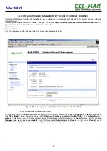
Page 14: ...below Fig 16 The web page for configuration and management of ADA 13021 5 2 1 NETWORK CONFIGURATION To make a changes of default setting or new configuration of ADA 13021 select on left panel Configur...

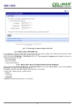
Page 15: ...configuration details page includes Port Profile Settings Basic Serial Settings Advanced Serial Settings 5 2 2 1 SERIAL PORT PROFILE CONFIGURATION OPERATING MODE Select on right panel Serial Port Conf...

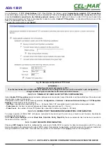
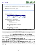
Page 16: ...the converter will be not taken what will cause the error message 5 2 2 1 2 TCP SOCKETS CONFIGURATION Choosing TCP Sockets is configured the serial port of ADA 13021 for direct communication with PC o...

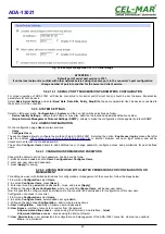
Page 17: ...ration of this option can be made by selection Configuration Network Advanced Network Settings TCP Keep Alive Settings In this section can be configured Idle Time specifies the period scope 10 sec 24...

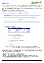
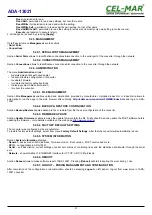
Page 18: ...ASTER device press Apply Fig 21 Example configuration of the UDP server client on converter connected to MASTER device 5 2 2 1 3 2 UDP CLIENT SERVER CONFIGURATION IN CASE OF SLAVE DEVICE Set operating...

Page 19: ...ge Fig 18 profile enable direct communication between two devices connected to two ADA 13021 converters over the network as if they were connected with a serial cable A properly configured ADA 13021 w...

Page 20: ...ry to enter user name and password The section Configure Users allows to add additional user change password configure access and permissions for each defined users 5 2 4 1 CHANGING USER MANE AND PASS...

Page 21: ...in the web browser after entering http address ip convertera FS WEB index htm and login to ADA 13021 5 2 6 2 BACKUP RESTORE CONFIGURATION Section Backup Restore enables backup to file or restore from...

Page 22: ...ill start the searching for converters in the network 8 if no devices were not found press Next 9 should be set in the window Describe the device IP address for wireless serial server number of instal...

Page 23: ...Fig 29 Devices view on Windows XP Fig 30 Example configuration of multi port serial adapter 23 ADA 13021...

Page 24: ...tart with default settings Restoring Default Settings deletes existing configuration and the proper configuration should be loaded to the converter form the backup I changed the configuration and the...

Page 25: ...interface Electrical Parameters Power requirements 10 24 30 V DC Power Cable Recommended length up to 3m Power 3W Protection from reverse power polarization yes Galvanic Isolation 1kV or 3kV between...

Page 26: ...26 ADA 13021...

Page 27: ...27 ADA 13021...

Page 28: ...a transmission converters with interface RS232 RS485 RS422 USB Current Loop Fibre Optic Converters and Ethernet or Wi Fi Please contact us to tell how you like our products and how we can satisfy you...

Reviews: