2.3.2. COMMUNICATIONS IN THE VIRTUAL SERIAL PORT MODE (RealPort)
Communication in the virtual serial port mode allows an application SCADA, MMI e.t.c., to transfer data to the serial port of the
converter via Ethernet network, by the use virtual COM port , created in an operating system.
2.3.3. COMMUNICATIONS IN THE SERIAL BRIDGE MODE
Communication in the serial bridge mode allows transferring data via Ethernet network between serial port of the converter's ports in
one-to-one topology or one-to-many by the use of client and server TCP/UDP services.
2.3.4. COMMUNICATIONS IN THE INDUSTRIAL AUTOMATION MODE (Modbus Gateway)
Communication in the MODBUS Gateway (IA) allows conversion of MODBUS-RTU master/slave protocol and MODBUS-ASCII
master/slave protocol to MODBUS-TCP protocol and inversely. It's let to integrate MODBUS-RTU/ASCII devices with MODBUS-TCP
devices in a single network.
2.3.5. OTHER COMMUNICATION TYPES
ADA-13021MG converter can be configured in other communication types, like:
– terminal mode,
– modem emulation mode,
– console mode,
– user mode.
However, in the case of the Current Loop converter, it will not be able to work properly in these modes, as they relate to the full RS232
interface.
2.4. CURRENT LOOP INTERFACE
2.4.1. CURRENT LOOP TRANSMITTER
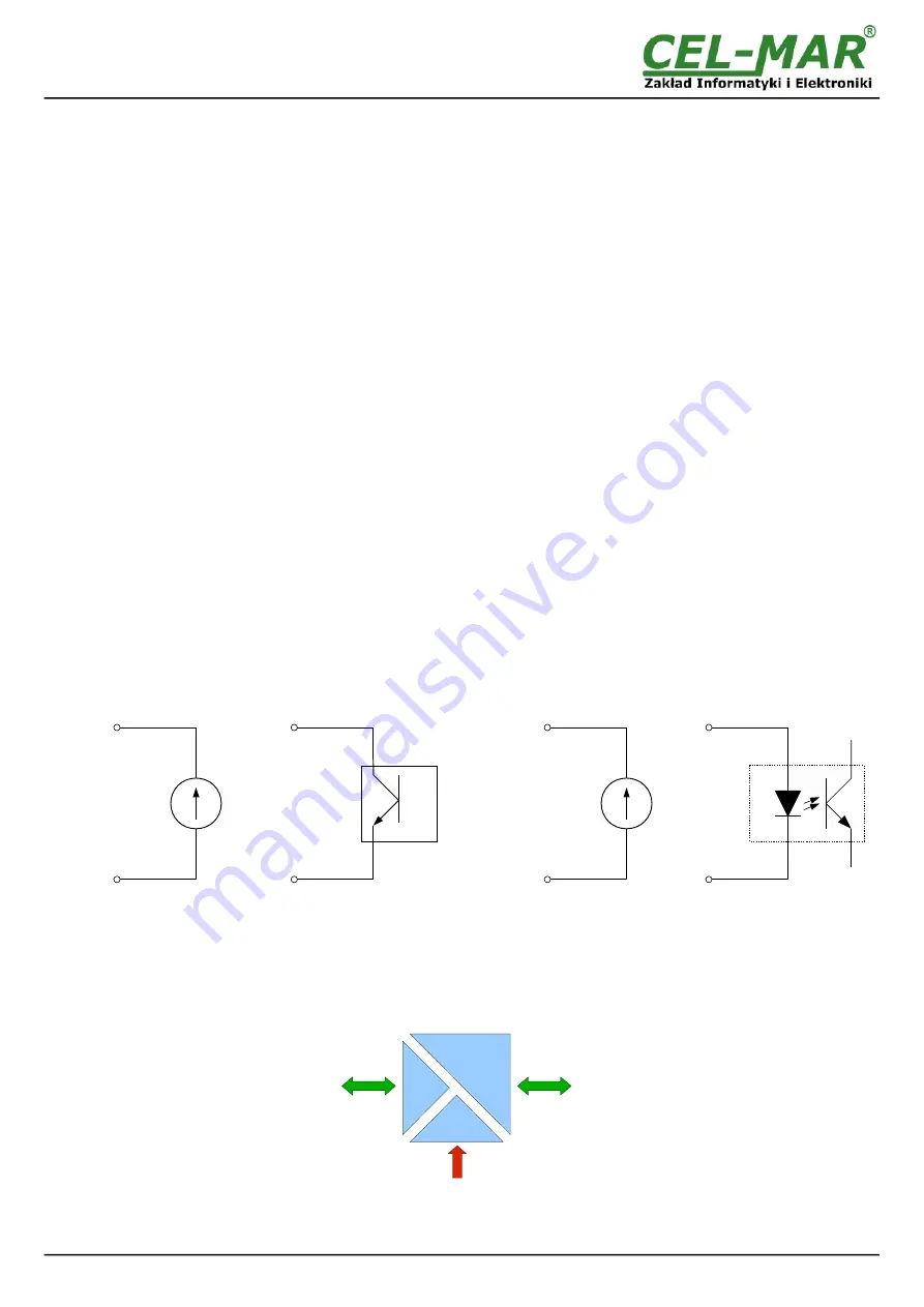
The Current Loop transmitter in ADA-13021MG was made as a passive 0-20mA(TTY), having low energy short circuit protection on
TX+ and TX- lines. By the correct connection of the transmitter with power source I1, Current Loop transmitter 0-20mA can operate as
active. The transmitter diagram is shown on figure below.
2.4.2. CURRENT LOOP RECEIVER
ADA-13021 converter has passive RX receiver having low energy short circuit protection on TX+ and TX- lines.
By the correct connection of the receiver with power source I2, Current Loop receiver 0-20mA can operate as active.
The receiver has signalization of non current flow through optocoupler. It is indicated by the red LED RX on front panel of the
converter. This LED lit when it is:
- not connect transmitter to receiver,
- wrong connection of transmitter to receiver,
- broken connection of transmitter to receiver.
The diagram is shown on figure below.
Fig. 3. Diagram of the transmitter & receiver ADA-13021MG Current Loop
2.5. ISOLATION
Converter ADA-13021MG has 3-way galvanic isolation on level 1kV= or 3kV=, depend on version described in section
VERSIONS
.
Fig. 4. Isolation structure
6
ADA-13021MG
Power Supply
10 - 30VDC
ETHERNET
Current Loop
3-WAY ISOLATION
I2 -
I= 0 / 20mA
I
I2 +
RX-
Passive Receiver
I2 – Receiver's
Current source
RX+
TX-
I= 0 / 20mA
TX+
Passive Transmitter
I1 -
I= 0 / 20mA
I
I1 +
I1 – Transmitter's
Current source


