Table below show preparing of cable with interlace for converter connection to network adapter of PC or converters together for
operating like point-to-point serial bridge.
Table 2.
RJ45 Pin No.
Signal
Wire Color
EIA/TIA 568B
Cross-Over Cable
UTP 4x2x0,5
Wire Color
EIA/TIA 568B
Signal
RJ45 Pin No.
1
TX+
White-Orange
White-Green
TX+
1
2
TX-
Orange
Green
TX-
2
3
RX+
White-Green
White-Orange
RX+
3
4
Not used
Blue
Blue
Not used
4
5
Not used
White-Blue
White-Blue
Not used
5
6
RX-
Green
Orange
RX-
6
7
Not used
White-Brown
White-Brown
Not used
7
8
Not used
Brown
Brown
Not used
8
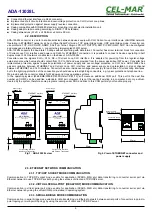
In modular socket ETHERNET interface of converter are implemented two LED's (Fig. 2):
–
Green ACT signaling state of sending or receiving data,
–
Orange LINK signaling active network connection.
ADA-13028L converter in the ETHERNET network can function as:
–
virtual serial bridge [RealPort],
–
TCP serial bridge,
–
UDP serial bridge.
Additional information about Ethernet connection will be describe in chapters below.
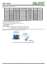
3.2.1. CONNECTING TO NETWORK ADAPTER OF PC
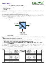
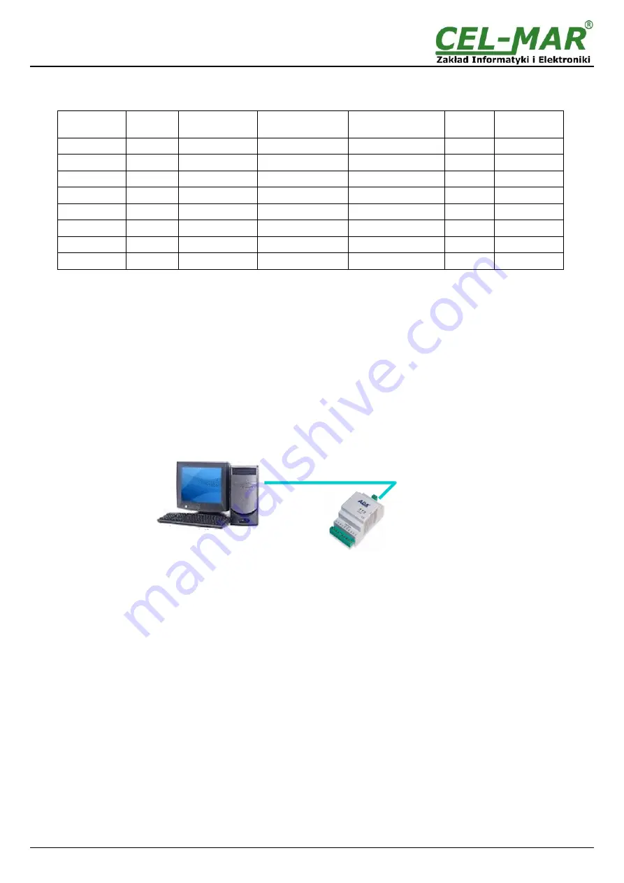
If there is not the switch or the HUB, it is possible to connect the ADA-13028L directly to a network adapter of PC using the cross-over
cable (Table 2). This connection can be used for converter configuration.
Fig 4. Direct converter connection to computer network adapter.
7
ADA-13028L
Computer with a
network adapter
Static IP address
ADA-13028L
Static IP address
ETHERNET
Interlaced Cable
(Tabela 2)

