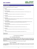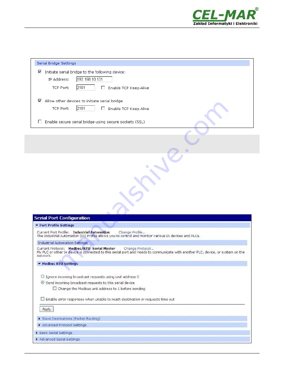
After saving the Serial Bridge profile, will open section
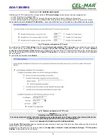
Serial Bridge Settings
with operating parameters like on picture below. Select
Initiate serial bridge to the following device
option and enter IP address and 2101 Port of ADA-13040MG with which to create the
serial bridge over the network. Additionally can be selected [
Enable TCP Keep-Alive
] option which keeps connection even if the data
is not transmitted. Select
Allow other devices to initiate serial bridge
and enter 2101 port on which other the converter will
automatically start communication and can be set also [
Enable TCP Keep-Alive
] option which keeps connection even if the data is
not transmitted.
Fig 21. Example configuration of TCP Serial Bridge
Attention !
Default port of serial port service is 2101.
If on the local network conflict with other network service using the same port, change number of port into another for the
service server of serial bridge and client in the server port configuration.
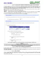
5.3.2.1.4.1. SERIAL PORT TRANSMISSION PARAMETERS
For proper operation of ADA-13040MG with device connected to his RS485/RS422 serial port, should be set the same transmission
parameters for both devices.
Select
Basic Serial Settings
and enter
Baud Rate
,
Data Bits
,
Parity
,
Stop Bits,
the same parameter like has device connected to
the Wireless Serial Server.
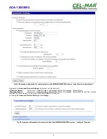
5.3.2.1.5. INDUSTRIAL AUTOMATION (MODBUS GATEWAY)
Choosing the
Industrial Automation (Modbus Gateway, Fig.16)
profile, will be possible to configure ADA-13040MG for
communication by the use of MODBUS-RTU master/slave or MODBUS-ASCII master/slave protocol. The Converter converts frames
of MODBUS-RTU/ASCII protocol to MODBUS-TCP and send via WLAN/LAN/WAN to devices with MODBUS-TCP protocol or other
servers ( ADA-14040, ADA14110, ADA-13040MG, ADA-13110MG) operating in
Industrial Automation (MODBUS Gateway)
mode
with connected MODBUS-RTU/ASCII devices. Press
[Apply]
for saving this profile.
Fig 22. Example configuration for operating with MODBUS-MASTER devices
19
ADA-13040MG

