background image

Functioning in modes: MODBUS-RTU Master/Slave and MODBUS-ASCII Master/Slave,

Power supply 10 - 30 VDC stable min. 3W,

~ 3000V= optoizolation in signal channel between ETHERNET and RS485/RS422 interface,

1000V= or 3000V= galvanic isolation between ETHERNET interface and power supply - depends on version,

1000V= or 3000V= galvanic isolation between RS485/RS422 interface and power supply - depends on version,

Connection RS485/RS422 interface via screw terminal block,

Implemented short circuit protection and over-voltage protection on RS485/RS422 network,

Protection against power supply reverse connection,

DIN 43880 standard - mounting in typical electro-installation unit,

Rail mounting according to DIN35 / TS35 standard,

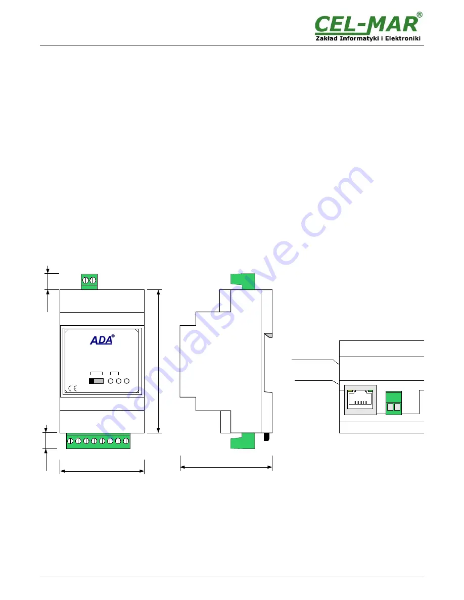
Dimensions (W x D x H) 53mm x 58mm x 90mm.

2.2. DESCRIPTION

The 

ADA-13040MG

 converter is used for data transmission between devices equipped with RS485/ RS422 interface via LAN/WAN 

network. In the ETHERNET network converter can operate in Virtual Serial Port mode, TCP serial bridge mode, UDP serial bridge 

mode, TCP sockets, UDP sockets and MODBUS Data Gateway . The MODBUS Data Gateway converts MODBUS-RTU master/slave 

and   MODBUS-ASCII   master/slave   protocol   to   MODBUS-TCP   and   inversely.   This   allows   for   integrate   MODBUS-RTU/ASCII   with  

MODBUS-TCP devices within one network.

Converter uses protocols: TCP, UDP, DHCP, SNMP, SSL/TLS, Telnet, Rlogin, LPD, HTTP/HTTPS, SMTP, ICMP, IGMP, ARP. It has a 

built-in WWW web server what allow you to configure and menage it via internet browser. The ADA-13040MG supports the baud rate  

230,4 kbps via RS485/RS422 interface and use RX+,RX-,TX+(A),TX-(B) signals. It is possible to connect 32 devices operating in half 

duplex mode to RS485 network constructed on the ADA-13040MG.

The Converter is adapted to supply an external voltage source fron 10V to 30V and power 3W. ADA-13040MG has implemented 

protection   against   opposite   polarization   of   power   supply   and   over-voltage   protection   on   RS485/RS422   network.   Converter   has 

galvanic isolation between ETHERNET and RS485/RS422 interface and power supply and optoisolation in signal channel between  

ETHERNET and RS485/RS422 interface.

We provide with converter the drivers which installed in the operating system (Windows 98ME,2000,XP,2003,Vista,7), will create an  

additional COM port. This port is the next free number eg COM3, can be used like a standard COM port. However it is not the real port  

existing in a computer, but only a virtual, created by the system, therefore some programs running under DOS and links to this COM 

port may not function properly.

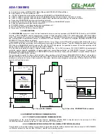
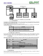
Fig 1. View of ADA-13040MG

    Fig 2. View of the  ETHERNET RJ45 connector

2.3. ETHERNET NETWORK COMMUNICATION

2.3.1. TCP/UDP SOCKED MODE COMMUNICATION

Communication  in  the  mode TCP/UDP sockets   allows  an  application   (SCADA, MMI) to  transfer  data  to the  serial   port of  ADA-

13040MG via Ethernet network by the use of  client and server TCP/UDP services.

2.3.2. COMMUNICATIONS IN THE VIRTUAL SERIAL PORT MODE (RealPort)

Communication in the virtual serial port mode allows an application (SCADA, MMI) to transfer data to the serial port of ADA-13040MG 

via  Ethernet network, by the use virtual COM port , created in an operating system.

5

ADA-13040MG

Network activity 

transmitting / receiving

Connection activity

8

1

-

+

58mm

(RS485/RS422)

N

C

N

C

N

C

G

N

D

T

+

 /A

T

/B

R

+

R

-

9

0

m

m

53mm

1

0

m

m

V

ss

-

V

ss

+

LINK

RST

(ETH)

ACT

1

0

m

m

ADA-13040MG

RS-485 / RS-422 to ETHERNET

CONVERTER with MODBUS GATEWAY

PWR

TX

RX

RS485/RS422

MODE

RS485

RS422

Summary of Contents for ADA-13040MG

Page 1: ...User manual ADA 13040MG ETHERNET to RS485 RS422 Converter with MODBUS GATEWAY 1 io_ada 13040MG_en_v0 10 ADA 13040MG Copyright 2001 2013 CEL MAR sp j...

Page 2: ...ATION AND MANAGEMENT WITH USE OF INTERNET BROWSER 13 5 3 1 NETWORK CONFIGURATION 14 5 3 2 SERIAL PORT CONFIGURATION 14 5 3 2 1 PORT PROFILE OPERATING MODE 14 5 3 2 1 1 REALPORT VIRTUAL PORT 15 5 3 2 1...

Page 3: ...AL PORT SERVICE REALPORT 24 6 1 VIRTUAL PORT DRIVER INSTALLATION IN WINDOWS XP 24 6 2 REALPORT CONFIGURATION IN WINDOWS XP 25 7 FACTORY DEFAULT 26 8 PROBLEMS 26 9 VERSIONS 27 10 DANE SPECIFICATION 27...

Page 4: ...wer supply circuit voltage Do not carry out the assembly or dis assembly of the device if it is enabled This may result to short circuit and damage the device 1 3 CE LABEL CE symbol on organizing the...

Page 5: ...32 devices operating in half duplex mode to RS485 network constructed on the ADA 13040MG The Converter is adapted to supply an external voltage source fron 10V to 30V and power 3W ADA 13040MG has imp...

Page 6: ...ing the converters form power circuit of devices generate large impulse disturbance like contactors relays inverters 3 1 ASSEMBLING The ADA 13040MG converter case is adapted to assembly on TS 35 DIN35...

Page 7: ...be used for converter configuration Fig 3 Direct connection to PC 3 2 2 CONNECTING FOR REALPORT MODE FUNCTIONING Fig 3 above and 4 5 below show how correctly connect the ADA 13040MG to LAN WAN networ...

Page 8: ...tion to functioning in the TCP UDP serial bridge mode one to one 8 ADA 13040MG Computer with a network adapter Static IP address ADA 13040MG Static IP address ETHERNET Straight cable Table 1 RS485 net...

Page 9: ...ng the ADA 13040MG 9 ADA 13040MG RS485 Bus MODBUS RTU ASCII SWITCH ETHERNET PC with SCADA HMI software M O D B U S T C P ADA 13040MG MODBUS Gateway ADA 13040MG MODBUS Gateway RS485 MODBUS RTU ASCII PL...

Page 10: ...e Connect wires of bus to terminals TX A TX B RX RX like below Fig 10 Connection of the RS485 4W devices to ADA 13040MG 3 3 3 CONNECTION TO 2 WIRE RS485 BUS Most of the devices with RS485 interface us...

Page 11: ...be longer than 3m Observe the polarity connect positive of DC power supplies to V and negative end to V terminal ADA 13040MG has the protection from opposite connection of power supply 4 ACTIVATION If...

Page 12: ...ble port servers Devices Fig 12 To change the network setting of ADA 13040MG should select the Converter from the list Devices and press Configure IP Settings in windows Set IP Address select option A...

Page 13: ...ices with use Internet browser For configuration open the Internet Browser and type the address http converter ip address admin administration htm The login windows will open Enter User name and Passw...

Page 14: ...13040MG converter includes port description setting of port profile operating mode and setting of serial transmission parameters baud rate data bits parity stop bits Select on left panel Configuratio...

Page 15: ...re present on his serial port The drivers RealPort installation is presented in chapter 6 Normally RealPort service allows for one connection through WLAN WAN between computer and server port Connecti...

Page 16: ...ction Establish connection to the following network service enter IP address of device to which TCP client will send data select service and enter port There is also possible to select an option Enabl...

Page 17: ...Apply for save 5 3 2 1 3 1 UDP CLIENT SERVER CONFIGURATION IN CASE OF MASTER DEVICE After saving the UDP Sockets profile will open section UDP Server Settings with operating parameters like on picture...

Page 18: ...ecommended to set parameters like on picture bellow For saving the configuration of UDP client and server for SLAVE device press Apply Fig 20 Example configuration of the UDP server client on converte...

Page 19: ...service server of serial bridge and client in the server port configuration 5 3 2 1 4 1 SERIAL PORT TRANSMISSION PARAMETERS For proper operation of ADA 13040MG with device connected to his RS485 RS42...

Page 20: ...like on Fig 22 and press Apply Then select section Slave Destinations Packet Routing fig below and press Add Section Destination Settings will open Fig 24 Example configuration for communication with...

Page 21: ...maximum delay or gap betweens bytes of a message default 20 ms Message timeout value in ms maximum delay or gap betweens bytes of a message default 2500ms this time must be less than the Timeouts set...

Page 22: ...ttings Global and set option e g as figure below and press Apply Fig 28 Example configuration for communication with MODBUS SLAVE Attention Default port of Industrial Automation Modbus Gateway is 502...

Page 23: ...ine Interface telnet Allow web interface access allow this user to access the web interface for system configuration and management C User Permissions user permissions associated with various services...

Page 24: ...ws2000 Operating systems Drivers WinXP2003Vista_x86_x64 for Windows XP Windows Server2003 Windows Vista Operating systems Installation of Virtual serial port drivers is as follow 1 Connect ADA 13040MG...

Page 25: ...ll be the name ADA 13040MG 5 Double click the name and the window Properties will appear 6 Select Advanced and press Properties 7 New name of virtual port for converter In the window Advanced Properti...

Page 26: ...according to steps below 1 Power OFF the ADA 13040MG 2 Remove the cover of Serial Server Wi Fi connector 3 Press RESET RST and holding the button turn the power on of ADA 13040MG 4 Release the button...

Page 27: ...x0 5 24AWG shield inside large interferences STP Nx2x0 5 24AWG Standards IEEE 802 3 EIA 485 CCITT V 11 Transmission line Asynchronism half duplex or full duplex Optical Signalization PWD green LED pow...

Page 28: ...r of the widest selections of data communications products in the world such as data transmission converters with interface RS232 RS485 RS422 USB Ethernet Wi Fi Current Loop Fibre Optic Converters and...

Reviews: