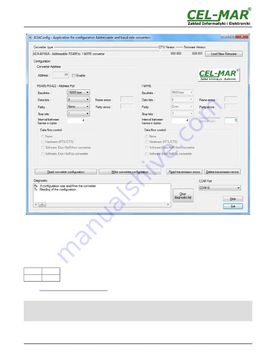
Fig. 10.
View of ADAConfig software interface
4.3. DATA TRANSMISSION DIAGNOSTICS
To readout diagnostics should be set SW1 microswitch to the configuration mode (see pt. 4.1.).
Correctness of transmission proceed on RS485/422 interface and 1-WIRE interface can be checked by readout the errors list by
ADAConfig
Software form the converter memory. Frames error counter will be increased, in case of: improper speed set compared to
real speed of data transmission. Parity error counter will be count the errors which can arise in case of misrepresent bytes in
transmitted sign. This counter will not works in case of disable control parity. To check those counters press the button
[Read
transmission errors],
and to delete (zeroing of counters in the memory of the converter) press
[Delete transmission errors].
In case of parity errors or frame errors, should be checked the ADA-401WA converter's configuration and correctness connection of
RS485 and 1-WIRE bus to the converter ports.
After finishing the diagnostics, the SW1 micro-switch should be set to run modeby using SW1 switch (yellow LED blink OFF) as below.
SW1-1
SW1-2
OFF
OFF
The test of communication with the converter in installation with sensors can be made by the use of tempf.exe – can be download
here>>>
http://cel-mar.pl/software/tempf_2.06.zip
.
4.4. FIRMWARE UPDATE
ATTENTION!!!
SOFTWARE VERSION 0004 AND HIGHER DO NOT WORK WITH CONVERTERS FROM THE CPU VERSION 1.0 AND 2.0.
TO UPDATE SOFTWARE TO VERSION 0004 AND HIGHER IN CONVERTERS WITH VERSION 1.0 AND 2.0 CPU PLEASE
CONTACT THE SERVICE.
Set SW1 micro switch to configuration mode as in table below.
9
ADA-401WA
Summary of Contents for ADA-401WA
Page 14: ...14 ADA 401WA ...
Page 15: ...15 ADA 401WA ...


